Hysteretic DC/DC converter

a converter and hysteretic technology, applied in the direction of code conversion, pulse technique, instruments, etc., can solve the problems of inherently produced delay, substantial increase of output voltage ripple, and introduction of further delay in the feedback loop, so as to achieve optimized converter performance and reliably control the delay time of the monostable circuit

Active Publication Date: 2008-09-02
TEXAS INSTR INC
View PDF9 Cites 13 Cited by
  • Summary
  • Abstract
  • Description
  • Claims
  • Application Information

AI Technical Summary

Benefits of technology

[0008]In a preferred embodiment, the gating circuit includes a gate and a monostable circuit, the gate having a first input connected to the output of the comparator, a second input connected to an output of the monostable circuit, and an output connected to the enable input of the converter power stage. The delay of the monostable circuit reliably determines the time span during which the output from the comparator is inhibited, i.e., prevented from being applied to the enable input of the power stage. Preferably, the monostable circuit has a trigger input connected to a feedback signal output of the converter power stage, the feedback signal from the feedback signal output having a first edge coincident with a starting current conversion pulse from the converter power stage and a second, opposite edge coincident with a terminating current conversion pulse from the converter power stage. This provides a precise timing of the gating operation.
[0009]In a further preferred embodiment, the monostable circuit has a variable delay time and a delay control input. The delay control input of the monostable circuit is connected to the output of the comparator through a low-pass filter. At the output of the low-pass filter, a signal indicative of the converter's output load is available. This signal is used to adjust the delay time of the monostable circuit in a closed feedback loop so that it remains shorter than time periods between successive current conversion pulses from the converter power stage under respective load conditions. In this way, the performance of the converter is optimized over a wide range of load conditions. Due to the low-pass filter characteristic of the feedback loop that defines the inhibit time, noise is filtered out in the feedback loop so that the delay time of the monostable circuit is controlled reliably.

Problems solved by technology

This substantially increases the output voltage ripple.
The resistive voltage divider at the output of the converter power stage may have parasitic capacitances which introduce further delay in the feedback loop.
In addition, with inductive boost converters, a delay is produced inherently since energy is transferred to the output in the OFF period of the power stage (in the ON period, the inductor is charged).
These phenomena separately and in conjunction cause pulse bursts to occur at the output of the power stage instead of single pulses, thereby introducing output voltage ripple.

Method used


Image

  • Hysteretic DC/DC converter
  • Hysteretic DC/DC converter
  • Hysteretic DC/DC converter

Examples


Embodiment Construction

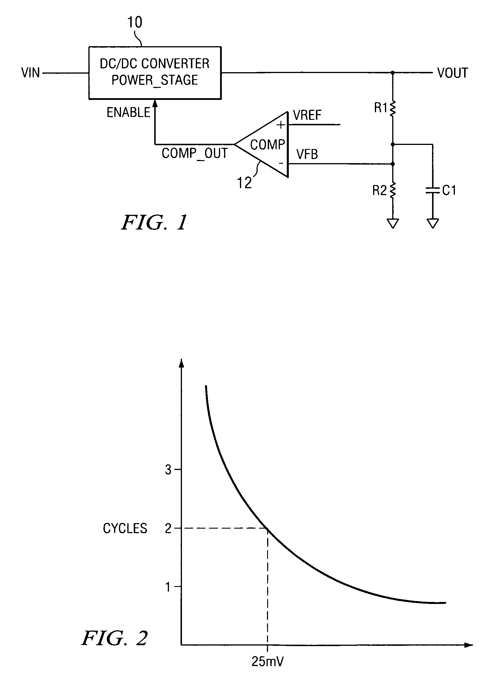
[0017]The conventional DC / DC power converter illustrated in FIG. 1 has a power stage 10 with a supply voltage input VIN, a controlled voltage output VOUT and an enable input ENABLE. A resistive voltage divider consisting of series-connected resistors R1 and R2 is connected between the output of power stage 10 and ground. A comparator 12 has a first input VFB connected to the node between resistors R1, R2 and receiving a feedback voltage, a second input VREF connected to a reference voltage source and an output COMP OUT connected to the ENABLE input of the power stage. The voltage divider inevitably includes a parasitic capacitor C1.

[0018]As seen in FIG. 2, the smaller is the comparator overdrive, i.e. the voltage difference between its differential inputs, the larger gets its propagation delay. For example, at high switching frequencies of the converter, an overdrive voltage of 25 mV may result in a propagation delay equal to two switching periods of the converter. It is thus unders...


PUM


Abstract

A hysteretic DC / DC converter is proposed that operates at a high switching frequency without producing undesired pulse bursts at the output. The converter has a converter power stage with a supply voltage input, a controlled voltage output and an enable input. A comparator has a reference voltage input, a feedback input and an output, and a gating circuit connected between the output of the comparator and the enabling input of the converter power stage. The gating circuit inhibits as a function of load requirements the propagation of enabling pulses from the output of the comparator to the enabling input of the converter power stage. By gating the output of the comparator in a way to separate the output from the enabling input of the converter power stage immediately after the start of each conversion pulse, the generation of further pulses immediately after each conversion pulse is prevented, thereby keeping the output voltage ripple low.

Description

[0001]The present invention relates to a hysteretic DC / DC converter operating at a high switching frequency.BACKGROUND OF THE INVENTION[0002]A DC / DC converter has a comparator that compares a fraction of the output voltage of the converter with a reference voltage and applies an enable signal to the converter power stage when the output voltage is lower than the reference voltage. In response to the enable signal, the power stage of the converter supplies conversion pulses to a load. At high switching frequencies, the propagation delay of the comparator increases with decreasing input overdrive (the voltage difference between the positive and negative inputs). When the propagation delay becomes longer than the switching period, the converter can no more react in the same cycle, and an additional conversion pulse is produced. As a result, multiple conversion pulses (bursts) are produced instead of single pulses. This substantially increases the output voltage ripple. A rough calculat...

Claims


Application Information

Patent Timeline
Patent Type & Authority Patents(United States)
IPC IPC(8): G05F1/40
CPCH02M3/156
Inventor BAYER, ERICH
Owner TEXAS INSTR INC
Why Eureka
Try Eureka