Scannerless loss modulated flash color range imaging

Active Publication Date: 2008-09-02
NAT TECH & ENG SOLUTIONS OF SANDIA LLC
View PDF11 Cites 39 Cited by
  • Summary
  • Abstract
  • Description
  • Claims
  • Application Information

AI Technical Summary

Problems solved by technology

These approaches are necessarily restricted to determining range information by processing multiple monochromatic images of a given wavelength

Method used


Image

  • Scannerless loss modulated flash color range imaging
  • Scannerless loss modulated flash color range imaging
  • Scannerless loss modulated flash color range imaging

Examples


Embodiment Construction

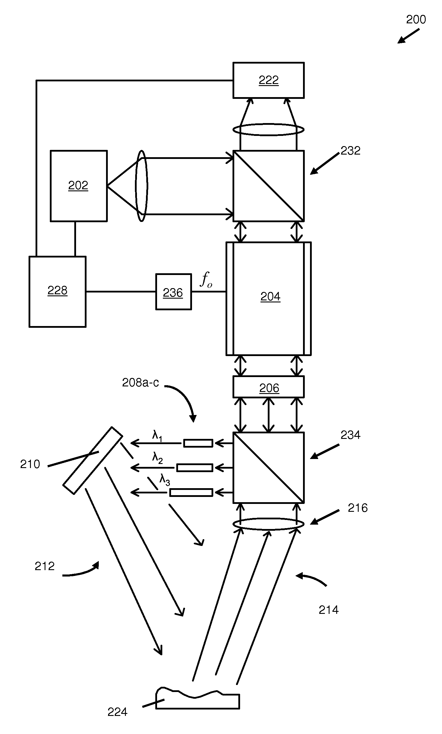
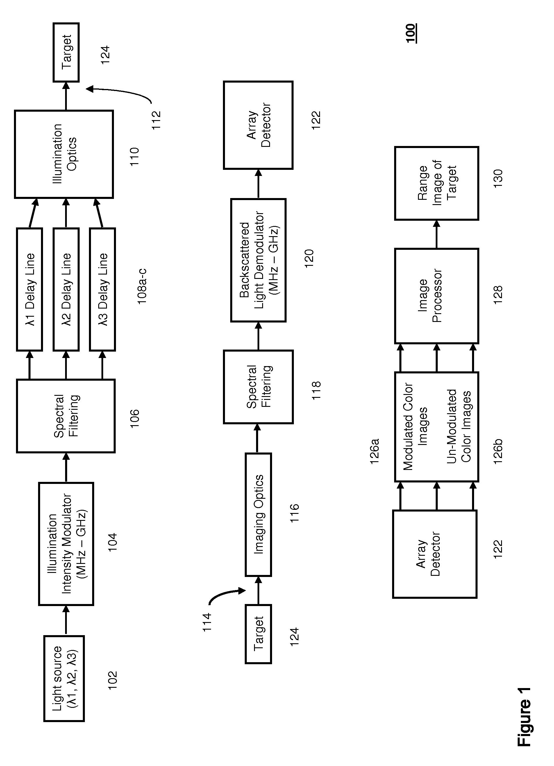
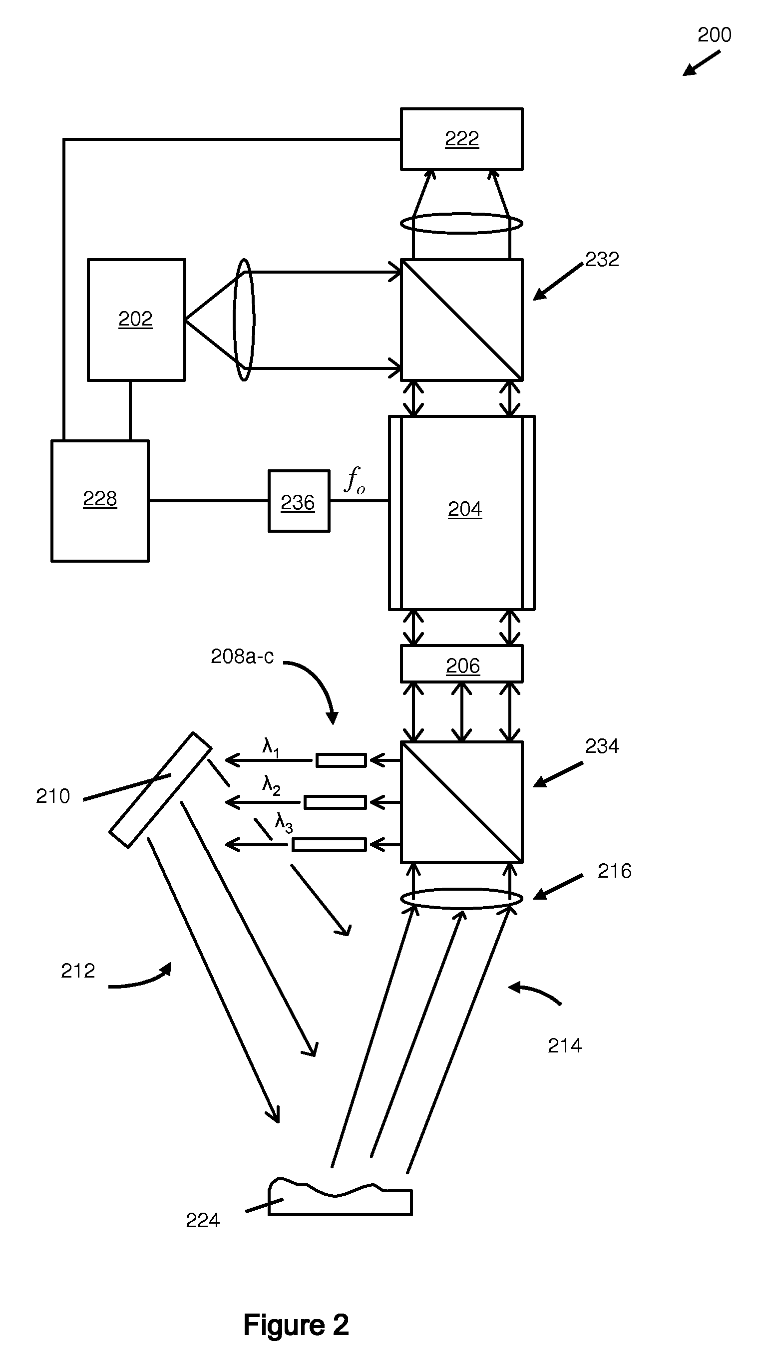
[0009]FIG. 1 is a schematic block diagram of an embodiment of a scannerless loss modulated flash color range imaging apparatus according to the present invention. Apparatus 100 comprises light source 102 adapted to simultaneously emit at least three wavelengths e.g. λ1, λ2, λ3 of light for continuous or flash, non-scanned illumination of a target 124. Light source 102 can comprise a broadband light source, for example a xenon lamp, or can as well comprise an array of laser sources or light emitting diodes (LEDs), i.e. arrays of monochromatic sources of various desired wavelengths. Light source 102 can be operated in a continuously emitting mode to illuminate the target 124 or as well can be operated in a flash mode, whereby the target is illuminated by a flash of light lasting from on the order of a microsecond to on the order of 100's of microseconds. Flash illumination of the target 124 can be utilized in applications where it may be desired to maintain “eye-safe” levels of illumi...


PUM


Abstract

Scannerless loss modulated flash color range imaging methods and apparatus are disclosed for producing three dimensional (3D) images of a target within a scene. Apparatus and methods according to the present invention comprise a light source providing at least three wavelengths (passbands) of illumination that are each loss modulated, phase delayed and simultaneously directed to illuminate the target. Phase delayed light backscattered from the target is spectrally filtered, demodulated and imaged by a planar detector array. Images of the intensity distributions for the selected wavelengths are obtained under modulated and unmodulated (dc) illumination of the target, and the information contained in the images combined to produce a 3D image of the target.

Description

STATEMENT REGARDING FEDERALLY SPONSORED RESEARCH OR DEVELOPMENT[0001]The United States Government has certain rights in this invention pursuant to Department of Energy Contract No. DE-AC04-94AL85000 with Sandia Corporation.FIELD OF THE INVENTION[0002]The invention generally relates to scannerless, loss modulated, flash color range imaging. The invention further relates to methods and apparatus for producing three-dimensional (3D) images of a target illuminated by at least three wavelengths of light, each wavelength being loss modulated and having an impressed phase delay, wherein backscattered light from the target is loss demodulated and received by an array detector and converted to an electrical signal, wherefrom information related to the demodulated intensity of each wavelength of phase delayed light is combined to determine the range to the target.BACKGROUND OF THE INVENTION[0003]Previous three-dimensional range imaging systems typically illuminate a target with a modulated mo...

Claims


Application Information

Patent Timeline
IPC IPC(8): G01C3/08
CPCG01C3/08G01S17/894
Inventor SANDUSKY, JOHN V.PITTS, TODD ALAN
Owner NAT TECH & ENG SOLUTIONS OF SANDIA LLC
Why Eureka
Try Eureka