
Modem relay over packet based network

a packet based network and relay technology, applied in the field of communication systems, can solve the problems of substantial reduction of achieve the effects of reducing power consumption and memory consumption of the gateway, reducing the bandwidth utilization of the packet based network, and reducing the time differen

Inactive Publication Date: 2008-09-02
SURF COMM SOLUTIONS
View PDF30 Cites 17 Cited by
  • Summary
  • Abstract
  • Description
  • Claims
  • Application Information

AI Technical Summary

Benefits of technology

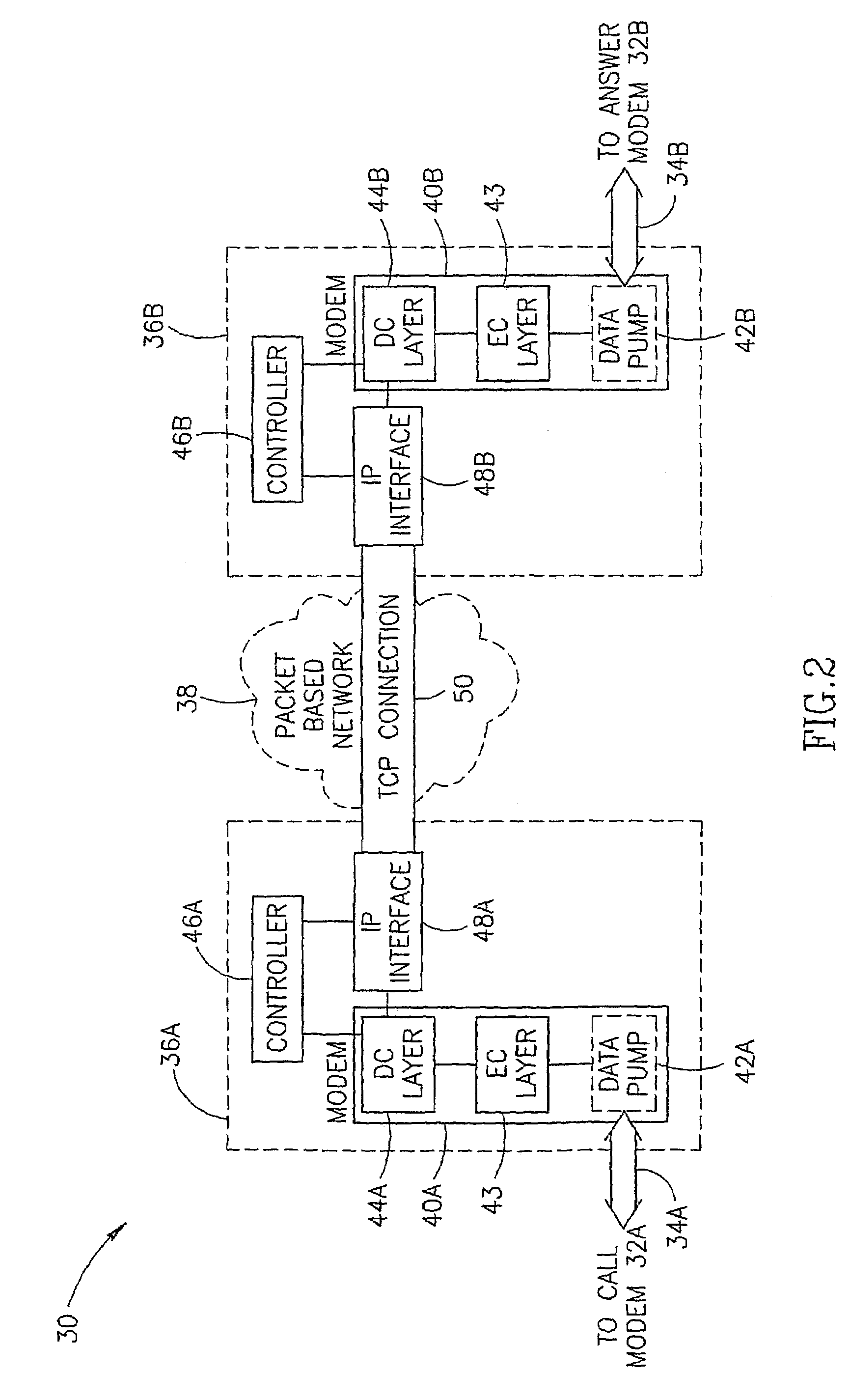
[0025]In other embodiments of the invention, the gateways perform partial termination, i.e., they perform data pump termination and partial or complete error correction (EC) termination but do not perform data compression termination, on their respective VBM connections. Also in these embodiments, the VBM connections may operate at different rates and / or in accordance with different protocols. In addition, there may not be any need to mirror retrain or other events occurring on one of the connections to the other connection. In some of these embodiments, however, at least some of the parameters of the connections are correlated, so as to minimize the time difference between the transmission of the same data segment on the different VBM connections. Optionally, the entrance to the data phase of the VBM connections is synchronized between the connections, for example by at least partially correlating the data pump training signals on the VBM connections. Alternatively or additionally, compression parameters exchanged at the beginning of the data phase are passed between the gateways, such that both the VBM connections agree on the same compression parameters. Transmitting the signals on the packet based network in their compressed form reduces the bandwidth utilization of the packet based network. In addition, not performing DC termination substantially reduces power consumption and the memory consumption of the gateways.
[0026]In still other embodiments of the invention, the gateways perform only DP termination and do not perform error correction and data compression (ECDC) termination on their respective VBM connections. The bits received by the gateways are transferred intact to the other gateway and error correction and data compression are optionally managed by the end modems of the MoIP connection. Not performing error detection and data compression by the gateways substantially reduces the delay of the signals on the MoIP connection, without affecting the transmission speed.
[0029]Alternatively or additionally, the gateways lengthen the transmission time of one or more of the signals they transmit according to the standard they are using. For example, in the V.8 standard, instead of transmitting the JM signal immediately upon receiving a correct CM signal, the gateway continues to transmit the ANSam signal until it receives from the other gateway the information it needs in order to transmit the JM signal.
[0036]Performing the tasks of the remote access server (RAS) in a plurality of locations allows greater freedom in laying out apparatus of the RAS. For example, in some cases it is desired that modem connections be terminated as close as possible to the respective client modems, in order to conserve expensive switched telephone lines. In such cases, in accordance with embodiments of the invention, front end units which perform only some of the tasks of a modem RAS are positioned at a plurality of locations close to the client modems while the remaining tasks are performed by an upper layer unit at a central location. Thus, the volume and maintenance costs of the apparatus at the plurality of front end locations is reduced as they perform only some of the tasks. In addition, centralizing the handling of some of the tasks reduces the cost of the apparatus performing these tasks, as the utilization rate of apparatus at a central location is generally higher.

Problems solved by technology

In addition, not performing DC termination substantially reduces power consumption and the memory consumption of the gateways.

Method used


Image

  • Modem relay over packet based network
  • Modem relay over packet based network
  • Modem relay over packet based network

Examples


Embodiment Construction

[0131]FIG. 1 is a schematic illustration of a MoIP connection 30, in accordance with an embodiment of the present invention. A call modem 32A establishes a connection with an answer modem 32B, which connection is formed of three segments in series. In some embodiments of the invention, modems 32A and 32B are both server modems or both digital modems. Alternatively, one of modems 32A and 32B is a client modem and the other modem is a server modem.

[0132]A first segment of the MoIP connection passes on a switched network 34A between call modem 32A and a call gateway 36A. A second segment connects call gateway 36A and an answer gateway 36B through a packet based network 38. A third segment connects answer gateway 36B and answer modem 32B on a switched network 34B. In some embodiments of the invention, the first and third segments carry the same data signals, although they may carry different control signals. That is, if the data signals transmitted between modems 32A and 32B comprise, f...


PUM


Abstract

A method of performing a negotiation session on a modem connection. The method includes receiving a plurality of negotiation signals from the source modem, by a first gateway, forwarding at least some of the received negotiation signals from the first gateway to a second gateway, over a packet based network, receiving, by the first gateway, responses to the forwarded negotiation signals from the second gateway, forwarding the responses from the second gateway to the source modem, by the first gateway, and transmitting from the first gateway to the source modem, response signals to at least some of the received negotiation signals, without receiving a response to the at least some of the signals from the second gateway.

Description

RELATED APPLICATIONS[0001]The present application is a U.S. national application of PCT / TL01 / 00455, filed on May 21, 2001. This application is also related to PCT application PCT / IL00 / 00288, filed on May 21, 2000, PCT / IL00 / 00492, filed on Aug. 13, 2000, PCT / IL00 / 00657, filed on Oct. 17, 2000, the disclosures of all of which are incorporated herein by reference.FIELD OF THE INVENTION[0002]The present invention relates to communication systems and in particular to systems which utilize modems.BACKGROUND OF THE INVENTION[0003]Traditional telephone networks comprise switched networks, e.g., the public switching telephone network (PSTN) and ISDN lines, in which a physical link path is established between the end users of a call. The voice signals of the call are passed, generally in a time domain multiplexed (TDM) manner, on the physical link path. On the other hand, data networks, such as the Internet, are generally packet based networks.[0004]Due to the wide availability of switched ne...

Claims


Application Information

Patent Timeline
IPC IPC(8): H04L12/66H04LH04L12/28H04L12/46H04L29/06H04N1/00
CPCH04L12/4604H04L12/5692H04L29/06H04N1/001H04N1/00209H04L69/169H04L69/164H04L69/165H04L12/4633H04L69/24H04N2201/0024H04N2201/0025H04N2201/0039H04N2201/0086H04N2201/0093H04L69/16H04L12/2859H04L12/2898H04L9/40
Inventor SOMEKH, ORENFISHER, ABRAHAMDAHAN, UDIGRAIBER, GIL
Owner SURF COMM SOLUTIONS
Learn More