Self-adaption coupling system for single mode optical fiber based on two-dimensional scanning of optical fiber end surface

A single-mode fiber, fiber end face technology, applied in the coupling of optical waveguides, optics, optical components, etc., can solve the problems of phase response delay, low bandwidth utilization, etc., and achieve high positioning accuracy, fast scanning speed, and device motion. Low inertia effect

Active Publication Date: 2017-05-10
INST OF OPTICS & ELECTRONICS - CHINESE ACAD OF SCI
View PDF3 Cites 4 Cited by
  • Summary
  • Abstract
  • Description
  • Claims
  • Application Information

AI Technical Summary

Problems solved by technology

[0005] The technical problem to be solved by the present invention is: to overcome the low bandwidth utilization rate of the existing self-adaptive coupling system based on the SPGD algorithm and the fiber end face locator, and to overcome the problem of phase response delay in the high speed positioning process of the fiber end face of the existing system, A single-mode fiber adaptive coupling system based on two-dimensional scanning of the fiber end face is proposed

Method used


Image

  • Self-adaption coupling system for single mode optical fiber based on two-dimensional scanning of optical fiber end surface
  • Self-adaption coupling system for single mode optical fiber based on two-dimensional scanning of optical fiber end surface
  • Self-adaption coupling system for single mode optical fiber based on two-dimensional scanning of optical fiber end surface

Examples


Embodiment Construction

[0036] The present invention will be further described below in conjunction with the accompanying drawings and embodiments, but the protection scope of the present invention should not be limited thereby.

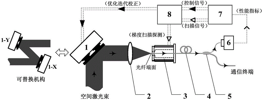
[0037] The overall structure and connection of the system are as follows: figure 1 As shown, it includes fast tilting mirror 1, coupling lens 2, fiber end face positioner 3, single-mode fiber 4, 1×2 fiber splitter 5, photodetector 6, control platform 7 and multi-channel high-voltage amplifier 8; space The laser beam is reflected by the fast tilting mirror 1 and then transmitted to the coupling lens 2. The end face of the single-mode fiber 4 under the control of the fiber end face positioner 3 is located at the rear focal plane of the coupling lens 2. The single-mode fiber 4 is divided into 1×2 fiber One output port of the 1×2 fiber optic splitter 5 is used to connect the communication terminal, the other output port is connected to the input port of the photodetector 6, an...


PUM


Abstract

The invention relates to a self-adaption coupling system for a single mode optical fiber based on two-dimensional scanning of the optical fiber end surface. The self-adaption coupling system comprises a rapid tilting reflection mirror, a coupling lens, an optical fiber end surface positioning device, a single mode optical fiber, 1*2 optical fiber branching device, a photoelectric detector, a control platform and a multi-channel high-voltage amplifier. According to the self-adaption coupling system, the efficient and stable coupling efficiency of space light and the single mode optical fiber is guaranteed; the optical fiber end surface positioning device is utilized for controlling the optical fiber end surface so as to realize the two-dimensional scanning of focused light spots, and the change rule of the power of light output by the optical fiber is monitored so as to calculate the optimization gradient of the coupling efficiency; and the rapid tilting reflection mirror is combined with an optimization algorithm, so that the self-adaption capturing tacking of the optical fiber end surface to the focused light spots is finished. The self-adaption coupling system has the innovation points that the optimization gradient detection is realized by virtue of the two-dimensional scanning of the optical fiber end surface to the focused light spots; the optimization gradient detection is separately executed with an iteration calibration process, so that the self-adaption coupling system has the advantages that the bandwidth availability ratio of a device is high, the Motion inertia is small, the tracking precision is high, the structure is compact, and the like; and the self-adaption coupling system has important application prospects in the communication field of space light.

Description

technical field [0001] The invention relates to an adaptive coupling system from a space laser to a single-mode optical fiber, belonging to the technical fields of automatic control and optical engineering. It has an important application prospect in free space laser communication. Background technique [0002] Free Space Optical Communications (FSOC) is a new type of communication technology developed in recent years with the advantages of high transmission rate, large information capacity, and good security performance. More and more mature optical fiber communication technologies are combined in the free space optical communication system, and its structural design becomes more flexible, the volume and weight are further reduced, and the stability is also greatly improved. -Mode Fiber, SMF) coupling has become one of the key technologies to be solved in this field. Limited by mechanical adjustment accuracy, ambient temperature, gravity and other factors, the position of...

Claims


Application Information

Patent Timeline
Patent Type & Authority Applications(China)
IPC IPC(8): G02B6/32G02B27/00
CPCG02B6/32G02B27/0031
Inventor 耿超黄冠李新阳李枫杨燕
Owner INST OF OPTICS & ELECTRONICS - CHINESE ACAD OF SCI
Why Eureka
Try Eureka