Air-bag assembly for a motor vehicle

a technology for airbags and motor vehicles, applied in the direction of vehicular safety arrangments, vehicle components, pedestrian/occupant safety arrangements, etc., can solve the problems of large airbag arrangement size, difficult manufacturing process, and large guide device complexity, and achieve the effect of compact form and simple manufacturing process

Inactive Publication Date: 2008-09-09
AUTOLIV DEV AB
View PDF17 Cites 31 Cited by
  • Summary
  • Abstract
  • Description
  • Claims
  • Application Information

AI Technical Summary

Benefits of technology

[0010]Furthermore, it is possible to set a pressure difference between the chambers, at least at a certain actuation time, by means of different degrees of expansion, different volumes of the chambers, or by directing different proportions of the gas stream to the chambers within a certain period of time.
[0011]Finally, it is possible to set a pressure difference between the chambers. This is achieved by configuring the distance between the impact / guide surface of the seam reinforcement and the outflow openings of the gas generator in a particular way by properly forming the open cross-section of the connection area between the chambers, by means of the expansion of the impact / guide surface, by contouring the impact / guide surface, or by means of an angle of slope of the impact / guide surface to the flow normals of the outflow openings.
[0012]Also, at least the impact / guide surface of the seam reinforcement is formed so as to be pressure and heat-resistant, to avoid component failure.
[0015]The proposed airbag arrangement is simple to manufacture, low-cost and very compact in form because a separate gas stream distributor is not included. In addition, the airbag arrangement is considered to be extremely reliable and also difference in pressure between the chambers in case of activation.

Problems solved by technology

A particular disadvantage of this arrangement is the difficulty of the manufacturing process and its associated cost, resulting from the complexity of the guide device.
In addition, this airbag arrangement is relatively large in size, requires a large amount of material and is therefore relatively heavy.
Here again, the high degree of complexity of the unit must be mentioned, resulting in an increased tendency of faults or disturbances.

Method used


Image

  • Air-bag assembly for a motor vehicle
  • Air-bag assembly for a motor vehicle
  • Air-bag assembly for a motor vehicle

Examples


Embodiment Construction

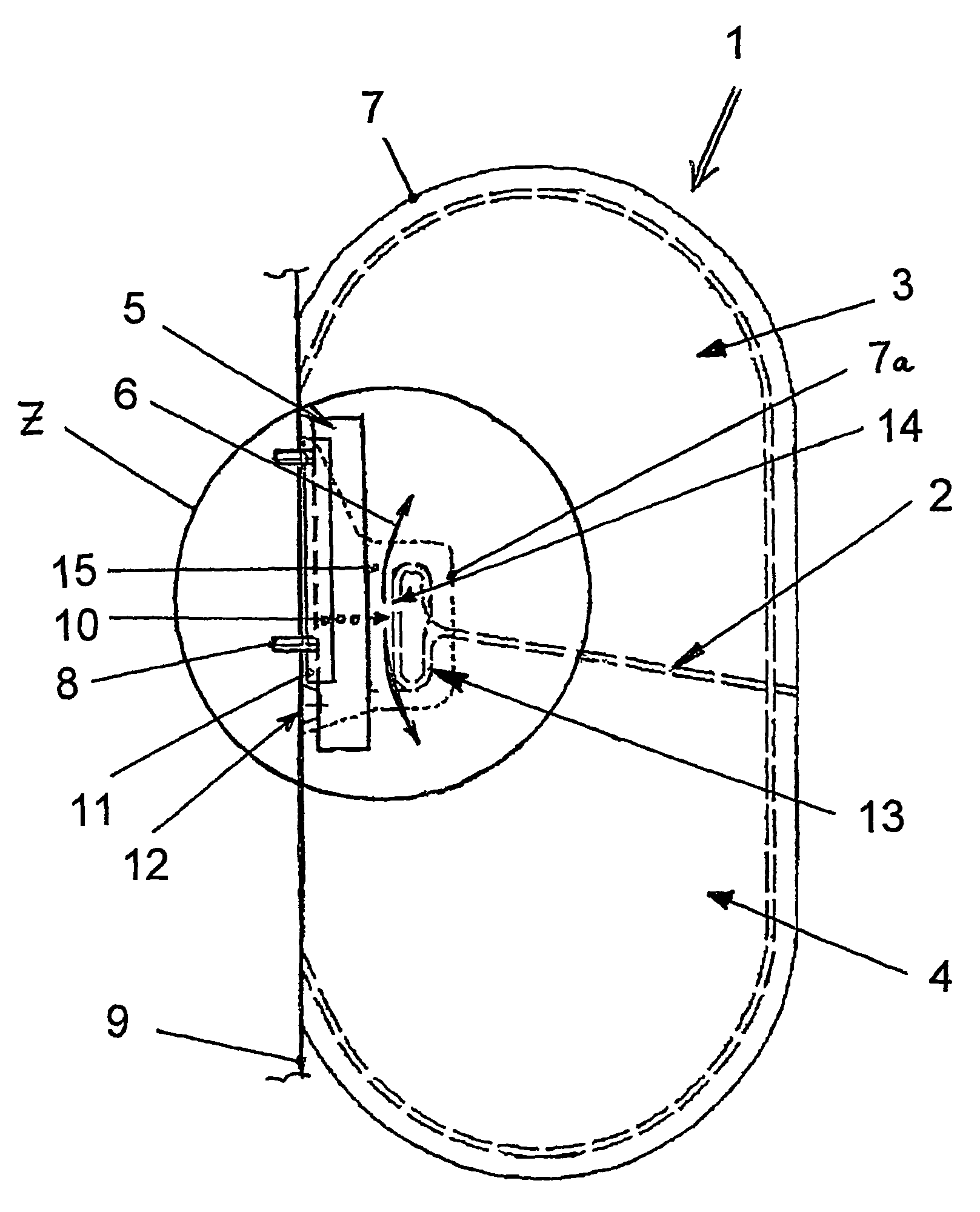
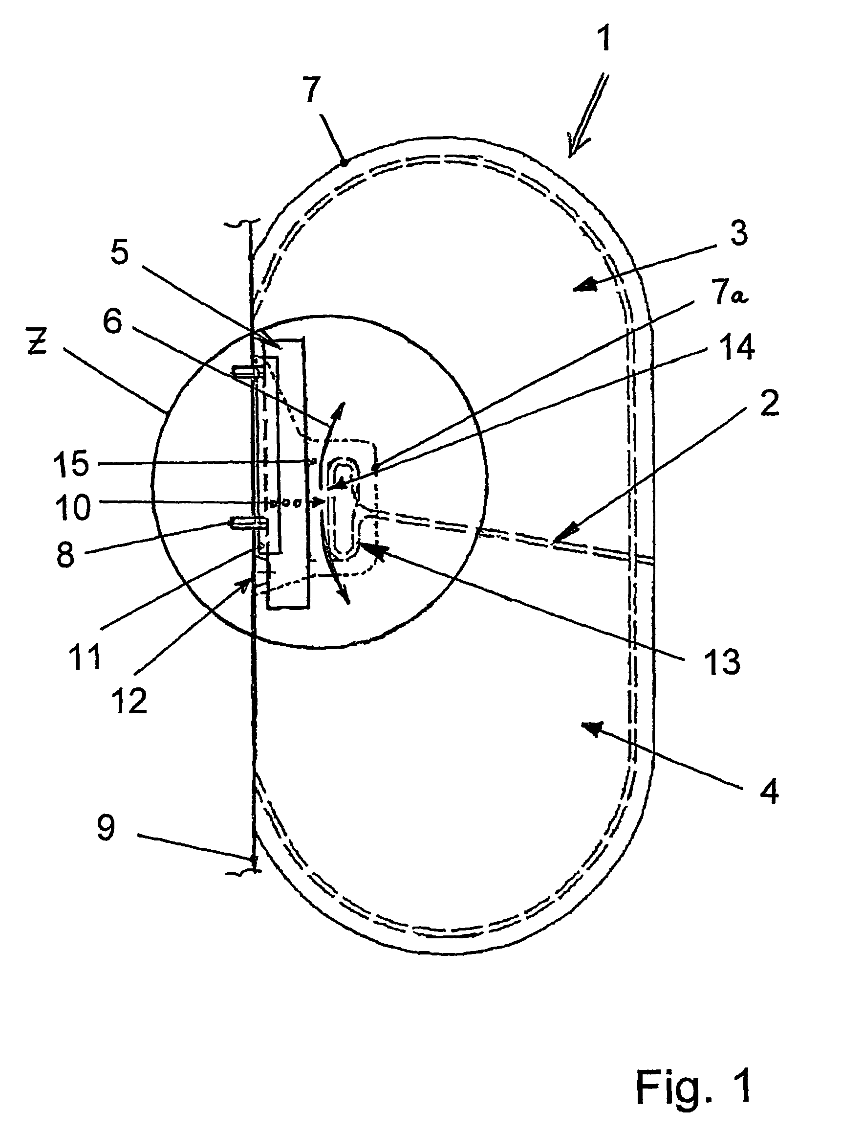
[0020]FIG. 1 shows an airbag formed in accordance with the present invention in an activated or deployed state and designated at 1. The airbag 1 is divided into two chambers 3 and 4 by means of a dividing seam 2 which is sewn through the two outer layers of fabric forming airbag 1. Other embodiments of the present invention may also include more than one dividing seam 2 and more than two chambers 3 and 4. In the embodiment according to FIG. 1, the lower chamber 4 is arranged relative to the pelvic area of a motor vehicle occupant (not shown) and the upper chamber 3 is arranged relative to the thorax area of the occupant.

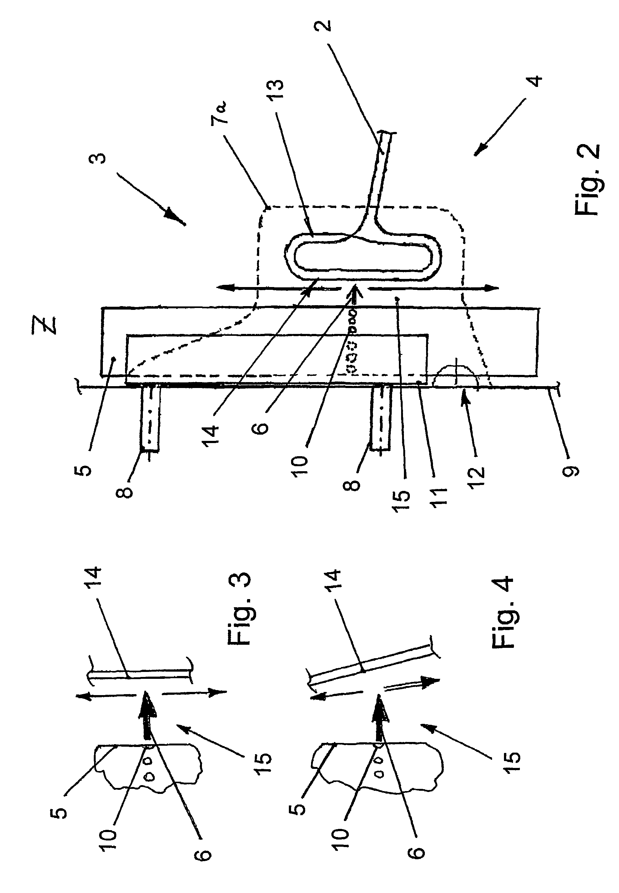
[0021]Furthermore, a gas generator 5 is arranged inside the airbag 1, and provides a propellant gas flow designated by arrows 6 for unfolding and inflation of the chambers 3 and 4. The gas generator 5 is fastened, for example to a module bracket 9 of the airbag 1, on or in the vehicle body (not shown), on or in a seat structure, for example the seat backrest (not sho...


PUM


Abstract

An airbag for use in motor vehicles having two or more chambers, which is simple to manufacture, low-cost and not susceptible to disturbances. The airbag is configured such that the chambers can have different internal pressures in case of airbag activation since a dividing seam between the chambers of the airbag is configured to act as a gas stream divider and direct differing quantities of gas into the chambers.

Description

CROSS REFERENCE TO RELATED APPLICATIONS[0001]This application claims priority to German application 10321066.0 filed May 10, 2003 and PCT / EP2004 / 004210 filed Apr. 21, 2004.FIELD OF THE INVENTION[0002]The present invention relates to automotive safety systems, and more specifically an airbag arrangement for use in a motor vehicle.BACKGROUND OF THE INVENTION[0003]Airbag arrangements have been state of the art within motor vehicle design and construction for a considerable time and, in addition to the safety belts which are already known, are a further component of the safety system intended to prevent vehicle occupants from coming into contact with the vehicle body structure or other vehicle components in the event of a collision.[0004]Multi-chamber airbag systems in which different chambers of the airbag are assigned to certain body areas of the vehicle occupants, have proven worthwhile. The individual chambers can include different volumes and internal pressures if a crash should oc...

Claims


Application Information

Patent Timeline
Patent Type & Authority Patents(United States)
IPC IPC(8): B60R21/21B60R21/207B60R21/16B60R21/233B60R21/26B60R21/261
CPCB60R21/233B60R2021/2612B60R2021/23316
Inventor HUBER, JOACHIMWITTMANN, ERNST
Owner AUTOLIV DEV AB
Why Eureka
Try Eureka