Image pickup system employing a three-dimensional reference object

a pickup system and reference object technology, applied in the field of image pickup systems employing three-dimensional reference objects, can solve the problems of high cost of apparatus, large image-picking facilities, and high measurement accuracy, and achieve the effects of high measurement accuracy, wide movable range, and high precision

Inactive Publication Date: 2008-09-09
MINOLTA CO LTD
View PDF20 Cites 55 Cited by
  • Summary
  • Abstract
  • Description
  • Claims
  • Application Information

AI Technical Summary

Benefits of technology

[0055]As described above, the present invention has been devised to solve the conventional problems, and its objective is to provide a technique for acquiring external parameters of a camera in such a manner that high measuring precision is obtained with a wide movable range being maintained by the use of an optical system, and also to achieve a technique for finding a three-dimensional shape of an object to be measured with high precision.

Problems solved by technology

However, in this fixed position method, since a plurality of cameras need to be fixedly placed in a dispersed manner inside an image-pickup studio, etc., it is necessary to provide a complicated, large image-pickup facility.
Among these methods, in the magnetic method, it becomes difficult to measure with high precision when the subject is made of metal, and the ultrasonic method results in high costs of the apparatus.
However, the plane chart has only a narrow angle range from which it can be observed, and it cannot be observed from directions exceeding 90 degrees from the normal direction of the plane chart; therefore, the camera movable range is extremely limited.
Moreover, even in the case when a camera is located within a range from which the plane chart can be observed, if the camera direction is greatly deviated from the normal direction of the plane chart, there is a reduction in the observation precision of the pattern, and the resulting problem is that the camera external parameter determining precision becomes poor.
In particular, when a subject is an object that is considerably larger than the plane chart, the conventional optical method fails to obtain accurate external parameters, resulting in a failure in composing a three-dimensional image model of the subject.
Moreover, in the technique of Japanese Laid-Open Patent Application No. 2000-270343, it is uncertain whether or not the obtained image has sufficient precision to be subjected to calculation processes at the time of the image-pickup process, and it is not possible to determine whether or not the image-pickup operation can be continued under the current state as it is; therefore, wasteful image-pickup operations tend to be carried out.

Method used


Image

  • Image pickup system employing a three-dimensional reference object
  • Image pickup system employing a three-dimensional reference object
  • Image pickup system employing a three-dimensional reference object

Examples


first preferred embodiment

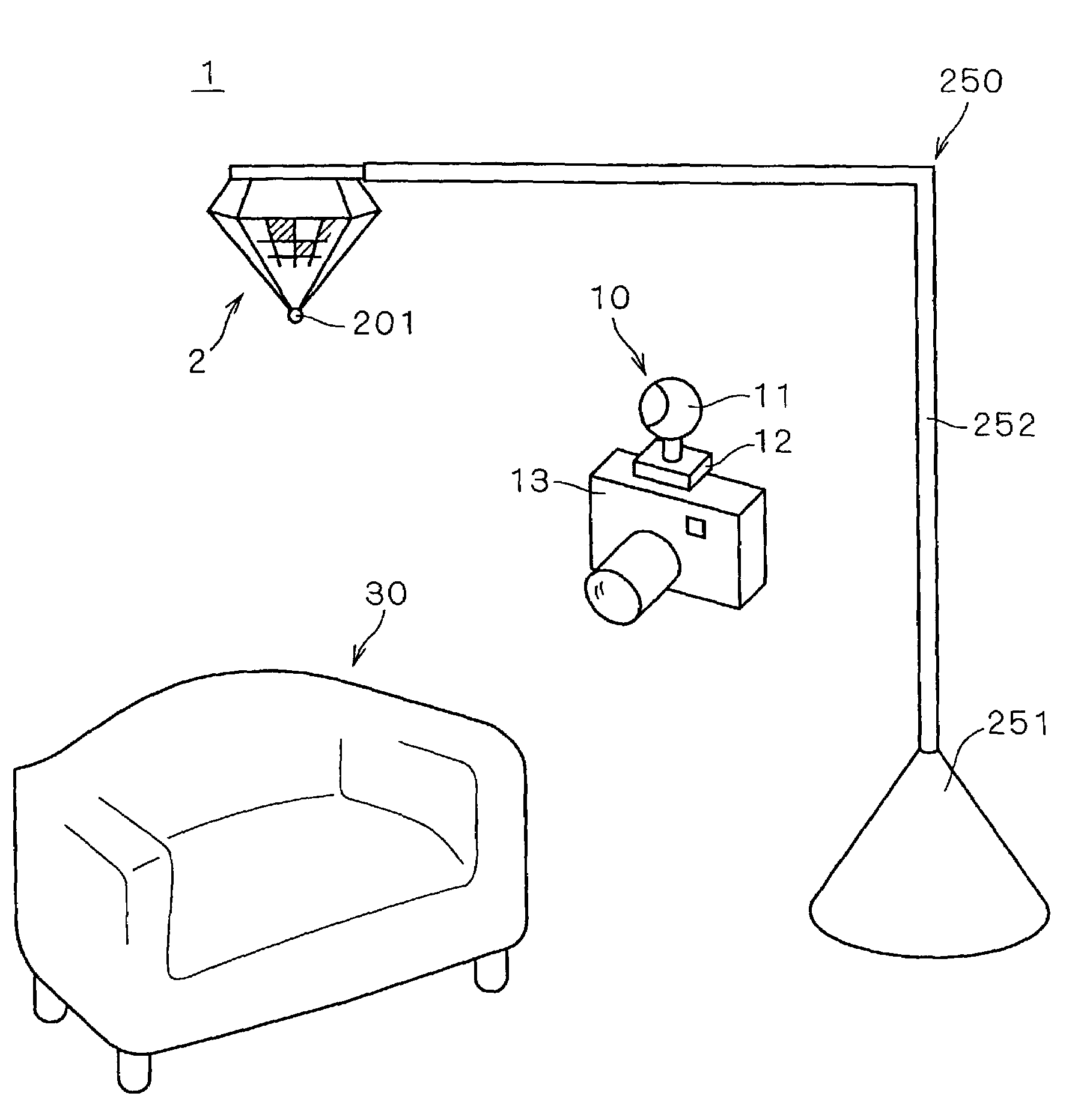
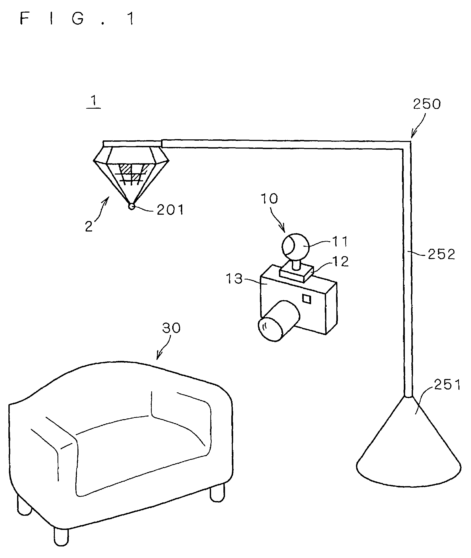
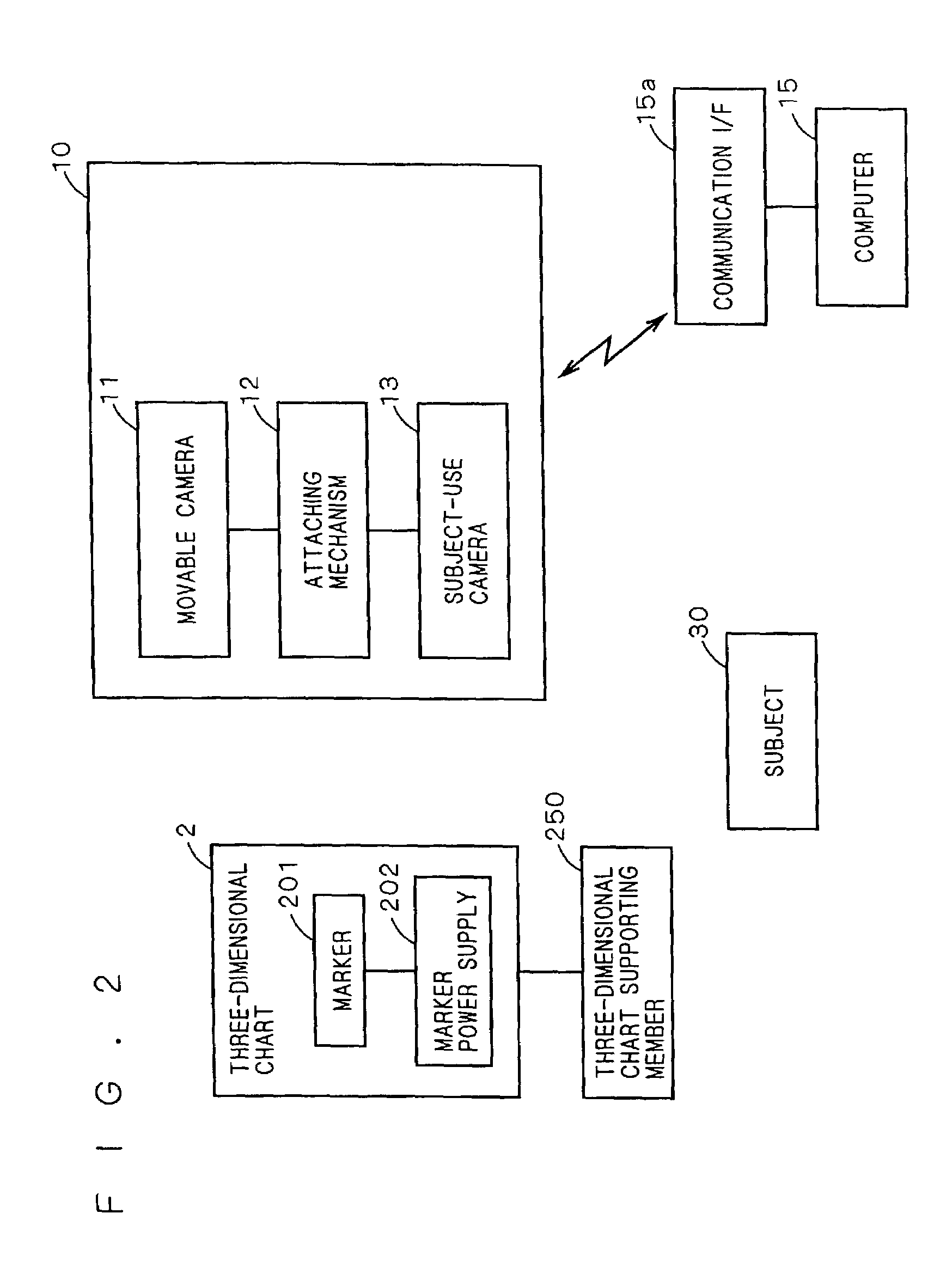
[0143]FIG. 1 is a drawing that shows a construction of an image-pickup system 1 (three-dimensional information generation system) that is achieved by the first preferred embodiment, and FIG. 2 is a block diagram that shows this image-pickup system 1. In FIG. 1, image-pickup system 1 is provided with a movable camera system 10 capable of picking up an image of a three-dimensional subject 30, and a camera-calibration-use three-dimensional chart 2 that is placed in the vicinity of subject 30 within a space including three-dimensional subject 30. Three-dimensional chart 2 is a reference object that has a known shape in the three-dimensional space, and constituted by a three-dimensional object in which a chart pattern is formed on each of the side faces of a main body having virtually a pyramid shape, as will be described later in detail. This three-dimensional chart 2 is suspended from a chart supporting member 250. This chart supporting member 250 is provided with an arm 252 having a r...

sixth preferred embodiment

[0484]The following description will discuss the sixth preferred embodiment of the present invention. In the fifth preferred embodiment, angle sensor 18 is fixed to subject-use camera 13; however, the method of detecting the absolute orientation with respect to a space is not limited to this. In the apparatus construction of the present preferred embodiment, angle sensor 18 is attached not to subject use camera 13, but to movable camera 11.

[0485]In the present preferred embodiment, although not shown in the Figure, angle sensor 18 is placed in a securing portion 114 (FIG. 4). FIG. 59 shows a block diagram of movable camera 11 in the present preferred embodiment, and FIG. 60 is a drawing that shows an essential portion of the information processing function of movable camera 11 from the viewpoint of hardware construction of movable camera 11. Moreover, FIG. 61 is a drawing that shows a flow of data in movable camera 11. Here, an essential portion of the information processing functio...

eleventh embodiment

11. Eleventh Embodiment

[0623]The following description will discuss an eleventh preferred embodiment of the present invention. In the present preferred embodiment also, a plurality of three-dimensional charts are placed on the periphery of subject 30, and it is possible to achieve a system which can construct a three-dimensional model with high measuring precision while maintaining a wide movable range. Here, the image pickup system in the present embodiment is virtually the same as the construction explained in the tenth preferred embodiment, and the detailed explanation thereof is omitted.

11>

[0624]FIG. 80 shows a block diagram that shows an inner function of movable camera 11. As shown in FIG. 80, in movable camera 11, a lens unit 110 and a two-dimensional light-receiving element 111 for photo-electric converting a two-dimensional image formed by this lens unit 110 are integrally housed in a spherical unit 116. Two-dimensional light-receiving element 111 is constituted by a CCD ar...


PUM


Abstract

The present invention provides a three-dimensional chart, a parameter acquiring method and an information processing device that are used for carrying out camera calibration in a wide range with high precision. For this reason, a plurality of unit graphic forms the sizes of which are coded by using different cross-ratios are placed on side faces of a three-dimensional chart. The cross-ratios of unit graphic forms are calculated from a picked-up image of the three-dimensional chart, and by collating these with actual values, the position and orientation of the image-pickup point are determined. The shifting average of the heights of the unit graphic forms is made approximately proportional to the distance from the apex so that it is possible to reduce the limitation of image-pickup distances. A movable camera is attached to a subject-use camera, and upon picking up an image of the subject, an image of the three-dimensional chart is also picked up simultaneously. Based upon the position and orientation of the movable camera found out by the above-mentioned sequence of image-pickup processes and the relative position and orientation between the two cameras that have been preliminarily found, it is possible to determine the position and orientation of the subject-use camera.

Description

[0001]This application is based on application Nos. 2001-157822, 2001-203375, 2001-203470, 2001-204720, 2001-206822, 2001-206823 and 2001-206824 filed in Japan, the contents of which are hereby incorporated by reference.BACKGROUND OF THE INVENTION[0002]1. Field of the Invention[0003]The present invention relates to a technique in which images of a subject is picked up from a plurality of directions to form a three-dimensional image model of the subject.[0004]2. Description of the Background Art[0005]Images of a three-dimensional subject are picked up from a plurality of directions, and a plurality of pieces of the resulting image data are composed so as to form a three-dimensional image model of the corresponding subject. In other words, when data such as camera external parameters (camera position, orientation, etc.) and inner parameters (focal length, etc.) are obtained for each of the respective images obtained by image-picking up the subject from a plurality of directions, a thr...

Claims


Application Information

Patent Timeline
Patent Type & Authority Patents(United States)
IPC IPC(8): H04N7/18G06T17/00H04N13/02H04N9/47H04N15/00H04N5/225G01B11/24G01C11/02G06F3/00G06F3/01
CPCG01B11/24G01C11/02G06F3/011G06T7/0044G06T7/0018G06T2207/30244G06T2207/30208G06T7/80G06T7/74
Inventor SAKAKIBARA, KUNITERUFUJII, EIROFUJIWARA, KOJI
Owner MINOLTA CO LTD
Why Eureka
Try Eureka