
High performance thermosiphon with internally enhanced condensation

a technology of thermosiphon and condensation, applied in the direction of lighting and heating apparatus, instruments, and semiconductor/solid-state device details, can solve the problem of relatively low air heat capacity, and achieve the effect of enhancing or increasing the enhancing the boiling efficiency of the assembly, and enhancing the condensing efficiency of the assembly

Active Publication Date: 2008-09-16
GULA CONSULTING LLC
View PDF6 Cites 26 Cited by
  • Summary
  • Abstract
  • Description
  • Claims
  • Application Information

AI Technical Summary

Benefits of technology

The invention is a cooling system for electronic devices that uses a refrigerant to transfer heat from the device. The system includes a mixing device within the housing to enhance the transfer of heat. This results in improved cooling efficiency, with the mixing device increasing the transfer of heat from the device to the refrigerant during the cooling cycle. The mixing device can be a stirrer or multiple stirrers, and can be positioned above or below the liquid refrigerant. The technical effect of the invention is improved cooling efficiency for electronic devices.

Problems solved by technology

These heat exchangers typically use air to directly remove heat from the electronic devices; however air has a relatively low heat capacity.

Method used


Image

  • High performance thermosiphon with internally enhanced condensation
  • High performance thermosiphon with internally enhanced condensation
  • High performance thermosiphon with internally enhanced condensation

Examples


Embodiment Construction

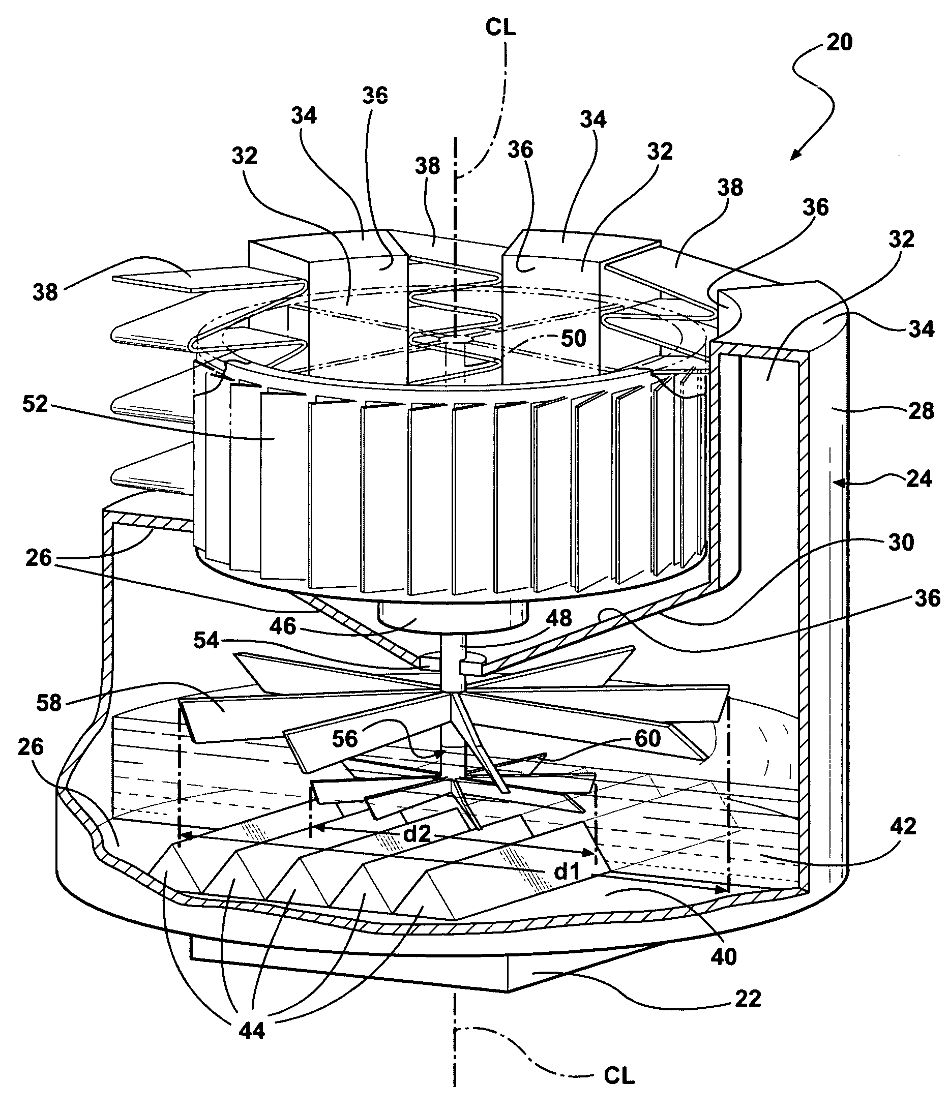
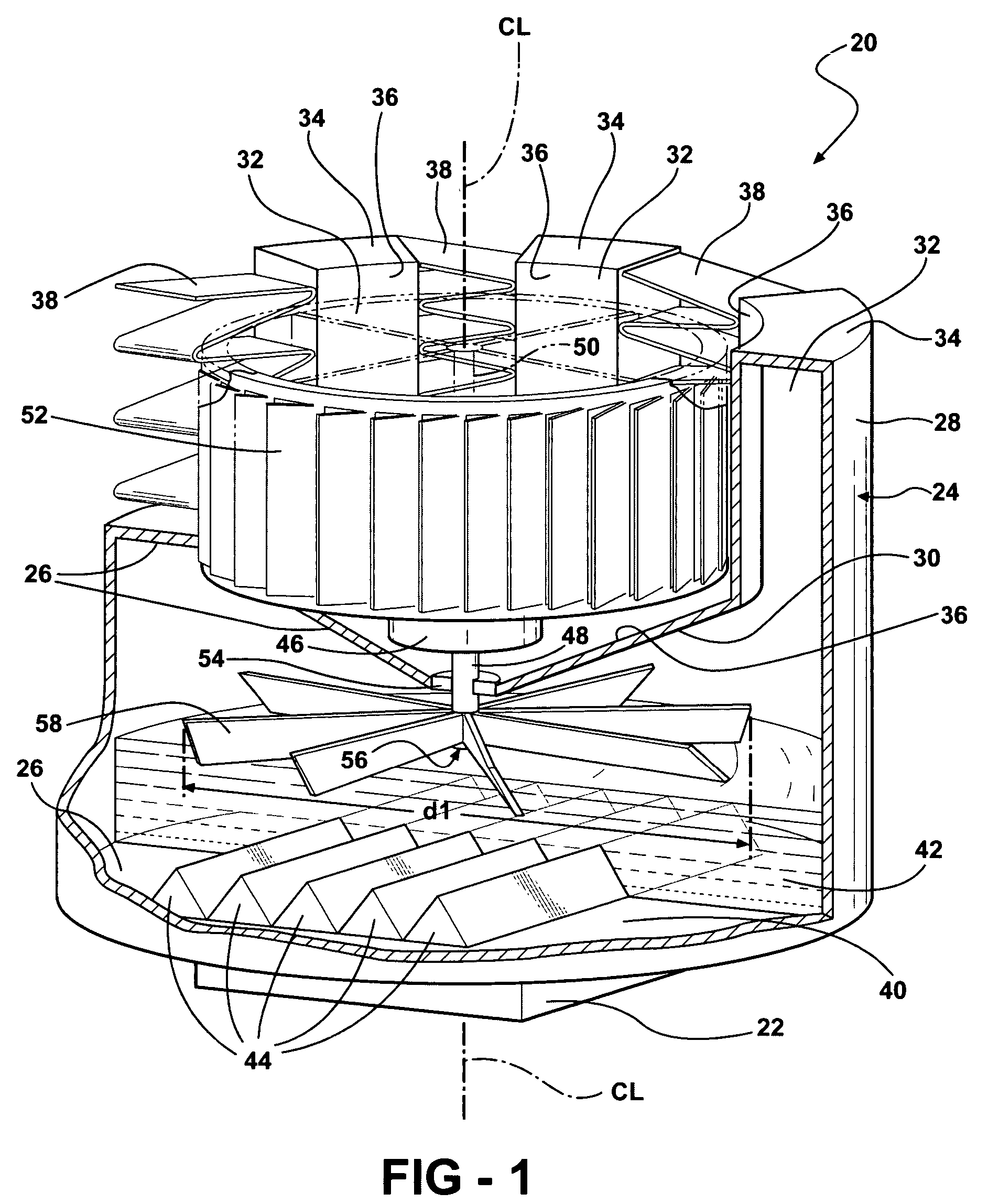
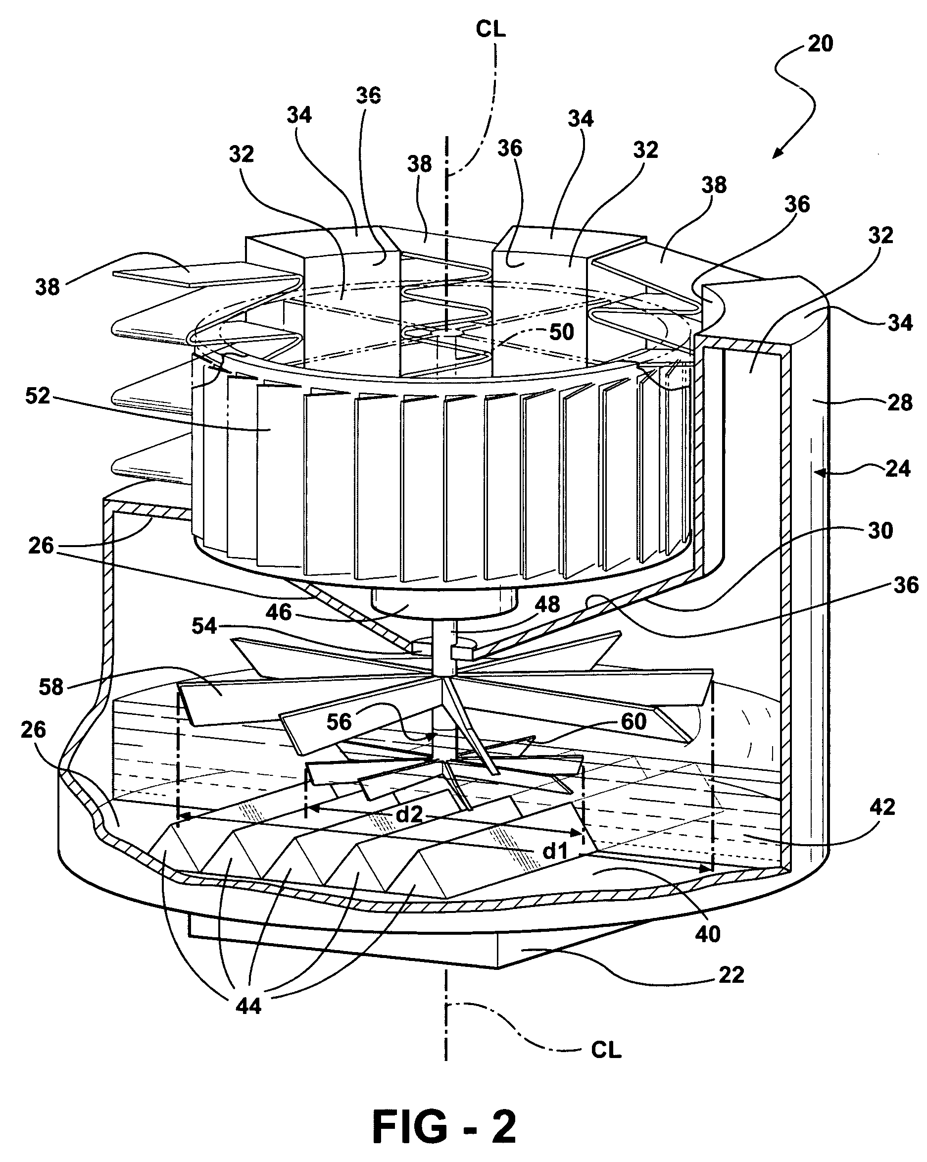
[0017]Referring to the Figures, wherein like numerals indicate corresponding parts throughout the several views, a thermosiphon cooling assembly 20 is generally shown for cooling an electronic device 22 in FIGS. 1 and 2.

[0018]The assembly 20 includes a housing 24 generally indicated having a lower portion 26 and an upper portion 28. The housing 24 defines a generally cylindrical periphery extending about a central axis CL. In addition to being generally cylindrical the housing 24 can be any shape known in the art, such as generally rectangular.

[0019]The lower portion 26 includes a conical top wall 30 extending upwardly and outwardly at an angle from the axis CL. The upper portion 28 includes a plurality of condensing tubes 32 that are spaced radially from and extend parallel to the axis CL. The condensing tubes 32 extend upwardly from and about the top wall 30 of the lower portion 26 of the housing 24 to a distal end 34. The condensing tubes 32 are spaced equally and circumferential...


PUM


Abstract

A thermosiphon cooling assembly includes a refrigerant disposed in a lower portion of a housing for undergoing a liquid-to-vapor-to-condensate cycle. A mixing device is disposed within the lower portion of the housing for increasing the transfer of heat from the electronic device during the liquid-to-vapor-to-condensate cycle. The mixing device may include a vapor stirrer disposed above the liquid of the refrigerant and / or a liquid stirrer disposed in the liquid of the refrigerant for moving the liquid of the refrigerant over a boiler plate.

Description

CROSS REFERENCE TO RELATED APPLICATION[0001]Co-pending application Ser. No. 11 / 406,617, filed Apr. 19, 2006 (DP-314469, DW 604080-00010) discloses and claims the patentably distinct concept of the configuration of disposing condensing tubes circumferentially about an axis. Although, the instant application discloses and claims the patentably distinct concept of mixing in the refrigerant cycle, the instant application illustrates this patentably distinct concept in a configuration which disposes the condensing tubes circumferentially about an axis.BACKGROUND OF THE INVENTION[0002]1. Field of the Invention[0003]The subject invention relates to a thermosiphon cooling assembly for cooling an electronic device.[0004]2. Description of the Prior Art[0005]The operating speed of computers is constantly being improved to create faster computers. With this, comes increased heat generation and a need to effectively dissipate that heat.[0006]Heat exchangers and heat sink assemblies have been use...

Claims


Application Information

Patent Timeline
Patent Type & Authority Patents(United States)
IPC IPC(8): F28D15/02
CPCF28D15/02F28F13/125G06F1/20H01L23/467H01L23/473F28D2015/0291G06F2200/201H01L2924/0002F28F2250/08H01L2924/00
Inventor BHATTI, MOHINDER SINGHREYZIN, ILYAJOSHI, SHRIKANT MUKUND
Owner GULA CONSULTING LLC
Learn More