
Three-dimensional visualization architecture

a three-dimensional visualization and architecture technology, applied in the field of virtual terrain architectures, can solve the problems of classic tiling schemes used for database paging that do not map well into the geocentric environment, and the data cannot be rendered in a geocentric coordinate system

Active Publication Date: 2008-09-16
MVRSIMULATION INC
View PDF9 Cites 7 Cited by
  • Summary
  • Abstract
  • Description
  • Claims
  • Application Information

AI Technical Summary

Benefits of technology

"The patent describes a method for creating a virtual terrain architecture using a geocentric coordinate system and tessellation of a polyhedron or spheroid for representing terrain data. The method involves subdividing a seed polyhedron into triangles, which are then individually indexed and stored in a database. Each triangular element is separately processed and rendered, allowing for separate processing and rendering of a geographical region that requires more than one triangular element. The system also allows for a perspective view from data stored in the database by defining a viewing frustum and tessellating the seed polyhedron. The technical effects of this patent include accurate representation of the earth's curvature and polar regions, efficient processing and rendering of geographical regions, and improved user experience for perspective view from data."

Problems solved by technology

One problem with such projection-based systems can be seen by looking at a world map.
Projection-based database generating systems do not create geocentric data, since these databases store data in two-dimensional space.
Similarly, the projection-based image rendering systems can not render data in a geocentric coordinate system due to the incompatibility of data types.
Furthermore, since there is no X-Y plane onto which the database has been projected in a geocentric coordinate system, classic tiling schemes used for database paging do not map well into the geocentric environment.

Method used


Image

  • Three-dimensional visualization architecture
  • Three-dimensional visualization architecture
  • Three-dimensional visualization architecture

Examples


Embodiment Construction

[0020]The following terms in this disclosure and the appended claims shall have the meaning presented here unless the context indicates otherwise. The term “terrestrial” and “terrestrial data” shall refer to land-based data. Terrestrial may refer to earth-based data or data from another celestial body. Terrestrial data case may include both imagery and elevation data. The term “pagable” shall refer to data within a computer imagery rendering system that can be independently rendered on a display device without accessing other stored data. Thus, a pagable primitive has associated data that can be rendered by a rendering engine by accessing the file containing the pagable primitive data. The term “perspective” or “perspective view” shall refer to at least the position, orientation, and field of view that are used by a rendering engine for rendering imagery. Additionally, a perspective may also include the maximum viewing distance. The term “spheroid” shall refer to a substantially sph...


PUM


Abstract

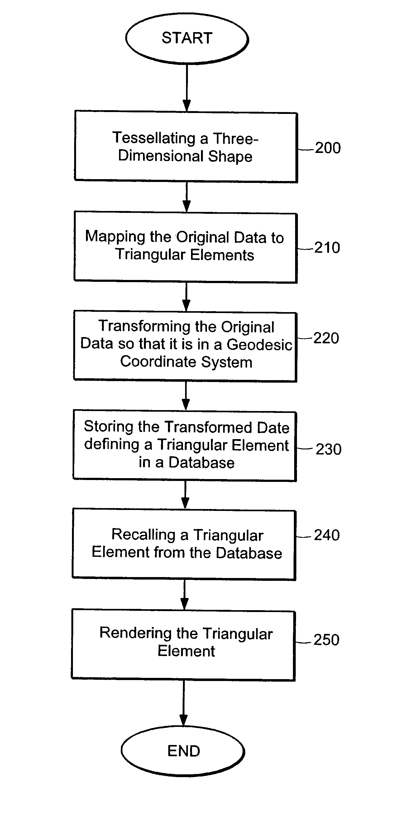
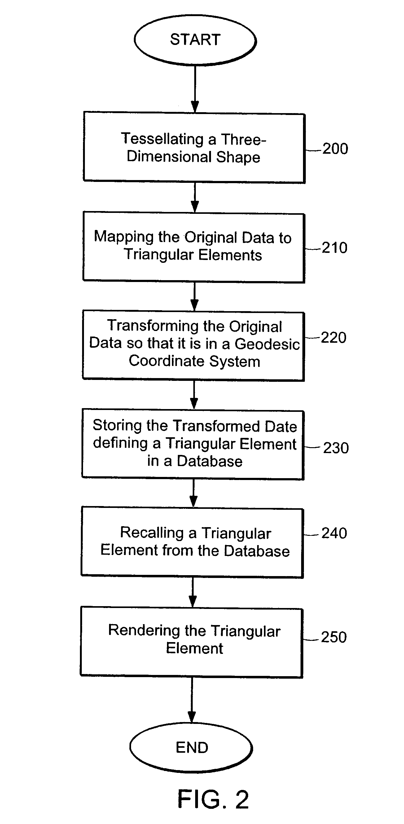
A virtual terrain architecture and computer program product for employing a geocentric coordinate system, using a tessellated three-dimensional shape for representing a celestial body, and mapping terrain data to the tessellated three-dimensional shape is disclosed. In one embodiment, the methodology begins with a seed polyhedron such as an ellipsoid model. The seed ellipsoid is preferably composed of a plurality of triangle primitives. After selection of the seed ellipsoid, the ellipsoid is subdivided using tessellation. Each triangular element is subdivided into four sub-elements which are also triangular in shape. As the elements are further subdivided, the triangles of the ellipsoid model create a sphere that is representative of the earth or other celestial body. Tessellation continues until a desired resolution is reached for each triangular element. Once a sphere has been substantially formed, terrain data is mapped to the triangular elements and the data is converted to geocentric coordinates and stored in a database. Each triangular element is separately indexed according to the triangular elements name. By creating a geocentric representation, the earth's curvature and polar regions can be accurately represented. By using a tessellation process, tiling for the geocentric coordinate system is achieved. Thus, the tiles can be paged as discrete elements.

Description

PRIORITY[0001]The present application claims priority from U.S. Provisional Patent Application 60 / 630,306 filed on Nov. 23, 2004 which is incorporated herein by reference in its entirety.TECHNICAL FIELD AND BACKGROUND ART[0002]The present invention relates to virtual terrain architectures for three-dimensional visualization.[0003]Virtual terrain databases for three-dimensional visualization are typically based on some type of map projection. Some common map projections used are Universal Transverse Mercator (UTM), Geodetic, Lambert Conic, and Flat Earth among several others. A database projection warps the curved surface of the earth onto a flat X-Y plane to create a local Cartesian coordinate system that simplifies the mathematics of a simulation.[0004]Projection-based database architectures typically subdivide the X-Y extents of a desired geographic region into small, uniformly-sized, rectangular areas commonly referred to as tiles or patches. The geographic coverage of the entire...

Claims


Application Information

Patent Timeline
Patent Type & Authority Patents(United States)
IPC IPC(8): G06T15/30G06K9/32G06K9/36G06T17/00G06T17/20
CPCG06T17/05
Inventor RYBACKI, RICHARD M.HANSEN, ANDREW J.
Owner MVRSIMULATION INC
Learn More