Powered aircraft including inflatable and rotatable bodies exhibiting a circular cross-section perpendicular to its rotation axis and in order to generate a lift force

a technology of rotating body and rotating cross-section, which is applied in the direction of influencers using rotating members, transportation and packaging, sustainable transportation, etc., can solve the problems of low amount of lift force generation, no prediction of neutralizing reaction force, and poor fuel economy of current invention, so as to achieve easy and cheap shipping/handling, generate significant lift force, and keep or carry in a very small space

Inactive Publication Date: 2008-09-23
SAEED TEHRANI OMID
View PDF25 Cites 6 Cited by
  • Summary
  • Abstract
  • Description
  • Claims
  • Application Information

AI Technical Summary

Benefits of technology

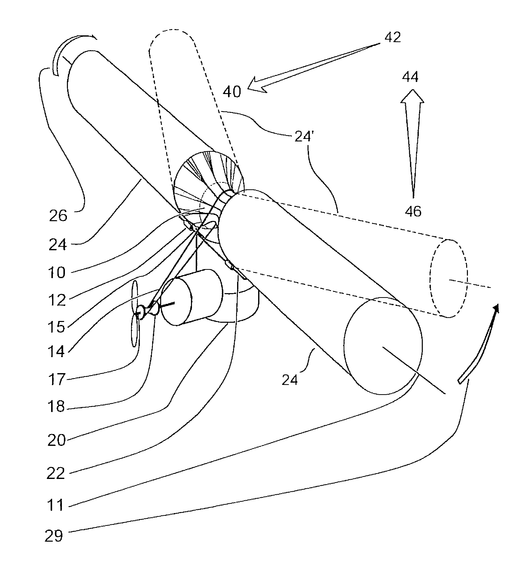
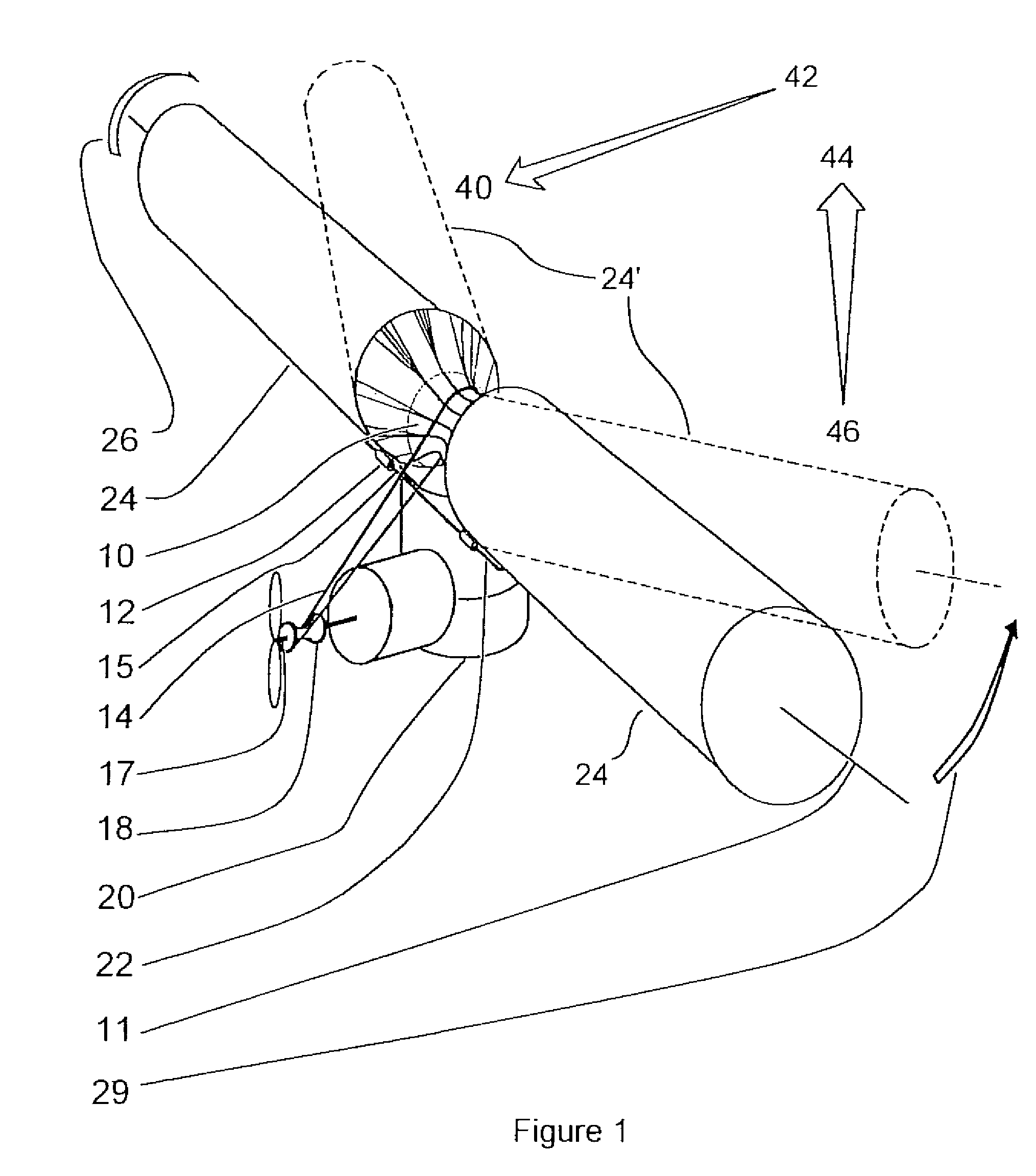
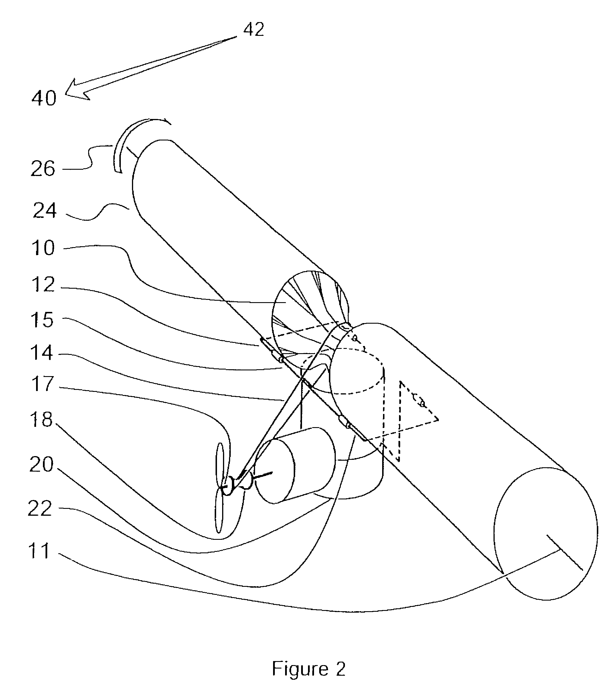
[0013]The rotating bodies are each further connected to and rotated by a pulley. The attachment to the pulley can be made rigid or flexible. The rotating bodies can be either rigid or flexible, if flexible allowing them to rotate, as well as bend backwards in a direction towards the fore to aft axis at high speeds, at their junction with pulley, thus resulting in decreased turbulence of the air at the back of the rotating bodies and ultimately a decrease in drag forces. The pulley connected to the rotating bodies is in turn connected by a belt to a further pulley installed on a shaft connected to the engine. The shaft runs lengthwise, in a direction generally consistent with the fore to aft axis, and from the engine to the propeller at the end.
[0023]Concurrent with the decreased need in runway space for takeoff, a yet further advantage of the current invention is the corresponding lesser requirement for a landing runway. As a result of the generation of more lift force at lower speeds by rotating bodies, it is possible that one can land at lower speeds and thus there is a lesser or no need for runway (such as again which makes possible vertical takeoffs and landings) depending on the rotation speed of the rotating bodies and the weight of the machine and its load (the heavier the load the more need for speed and the faster the rotation speed, the less the need for landing speed).

Problems solved by technology

Specifically, the current invention significantly reduces poor fuel economy and problems of acceleration to higher speeds associated with prior art Magnus effect rotor airfoils, by significantly decreasing drag forces associated with such acceleration.
In such instances, there is no prediction for neutralizing of the reaction force to the rotation of the rotating bodies by the engine.
Additionally, the lack of engine power in those designs causes a low amount of lift force generation.
Problems associated with earlier rotating airfoil devices include the low efficiency of rotating bodies in comparison to the conventional airfoils in generating lift forces with the same degree of energy input.
A secondary problem includes the turbulent flow that appears at the back of the rotating bodies, which especially increases forward speed, likewise increasing drag force and decreasing speed thereby preventing acceleration and leading to lower efficiency in lift force generation in comparison to the conventional airfoils.
Due to this problem, the machines which have been designed up to now have the problem of limited flying speed and acceleration in addition to the poorer fuel economy in comparison to conventional airfoil using aircrafts.

Method used


Image

  • Powered aircraft including inflatable and rotatable bodies exhibiting a circular cross-section perpendicular to its rotation axis and in order to generate a lift force
  • Powered aircraft including inflatable and rotatable bodies exhibiting a circular cross-section perpendicular to its rotation axis and in order to generate a lift force
  • Powered aircraft including inflatable and rotatable bodies exhibiting a circular cross-section perpendicular to its rotation axis and in order to generate a lift force

Examples


Embodiment Construction

[0035]Referring now to FIGS. 1-10, several variants are illustrated of a powered aircraft 10 which is capable of creating a lift-generating force through the provision of a plurality of rotatably driven rollers and according to Magnus effect physical principles. In particular, the present invention discloses an improved lift-generating aircraft which overcomes many of the drawbacks associated with the prior art Magnus effect lift devices.

[0036]Referring to FIG. 1, a perspective illustration is shown of an arrangement of lift-generating components according to a first preferred embodiment of the present invention and which includes a pair of lift force producing rotating bodies (illustrated at 24 and as will be discussed in further detail), each exhibiting an elongated and crosswise extending circular cross-section through which extends a centerline and crosswise extending axis 11. As will be described in additional detail, the rotating cylindrical shaped bodies 24 are preferably con...


PUM


Abstract

A lift force generating aircraft having an engine and a thrust force producing device. A pair of elongated and rotating bodies, an axial centerline through the bodies extending in a direction substantially perpendicular to a fore to aft axis extending between the engine and thrust-producing device and at a location above a center of gravity associated with the engine and thrust-producing device. The rotating bodies being constructed of a material inflatable to a desired pressure. A rotary output associated with the engine rotating the bodies, causing them to deflect to angles lesser than the perpendicular with the fore to aft axis, and in response to air stream forces acting upon the bodies in order to reduce drag forces experienced on a rear side of the rotating bodies.

Description

CROSS REFERENCE TO RELATED APPLICATIONS[0001]The present application is a continuation-in-part of U.S. application Ser. No. 10 / 709,493, filed May 10, 2004, now abandoned entitled “A Powered Aircraft Including Inflatable and Rotatable Bodies Exhibiting a Circular Cross-Section Perpendicular to Its Rotation Axis and In Order to Generate a Lift Force”.BACKGROUND OF INVENTION[0002]1. Field of the Invention[0003]This invention relates generally to aerodynamics and flight dynamics devices. More particularly, the present invention teaches a powered aircraft device incorporating substantially cylindrical shaped and power rotated components for creating lift. Specifically, the current invention significantly reduces poor fuel economy and problems of acceleration to higher speeds associated with prior art Magnus effect rotor airfoils, by significantly decreasing drag forces associated with such acceleration.[0004]2. Discussion of the Prior Art[0005]The present invention operates from the phys...

Claims


Application Information

Patent Timeline
Patent Type & Authority Patents(United States)
IPC IPC(8): B64C39/00B64C27/00
CPCB64C3/30B64C3/56B64C39/005B64C23/02Y02T50/145Y02T50/10
Inventor SAEED TEHRANI, OMID
Owner SAEED TEHRANI OMID
Why Eureka
Try Eureka