Aortic prosthetic devices

a prosthetic device and aortic valve technology, applied in the field of implantable prosthetic devices, can solve the problems of increased wall tension and myocardial oxygen demand, increased intraventricular pressure, and significant pressure drop across the valve, and achieve the effect of increasing the risk of obstructing or occluding

Active Publication Date: 2008-09-30
MEDTRONIC VENTOR TECH
View PDF75 Cites 589 Cited by
  • Summary
  • Abstract
  • Description
  • Claims
  • Application Information

AI Technical Summary

Benefits of technology

[0011]The present invention thus recognizes that the maximum orifice area of an implantable aortic valve stent is necessarily confined by anatomical and pathological limitations and subsequent concerns about the safety of deployment. The present invention therefore aims to reduce a permanent loss of pressure across any given cross sectional flow area of the prosthetic device. This allows achieving a reasonable hemodynamic profile (low pressure gradients) even for relatively small-sized prosthetic devices, as well as optimizing the hemodynamic profile (reduce pressure gradients even further) for larger devices. The invention thus effects pressure-recovery by streamlining the outlet geometry in order to avoid the occurrence of turbulence and kinetic energy dissipation as in a Venturi-meter.
[0013]The device may thus be provided in various sizes to accommodate different prosthetic sizes (e.g. 12 to 29 mm biological prostheses) so that patients of all possible height and body surface area can be treated.
[0015]As will be described more particularly below, such a construction is particularly useful for implantation in the aortic annulus of a patient's heart since it reduces the possibility of obstructing or occluding the coronary arteries, e.g., as compared to a prosthetic device requiring substantial expansion of the aortic annulus.

Problems solved by technology

The diminished aortic valve opening area (from normally 3 cm2 to less than 0.5 cm2 in severe cases) results in a significant pressure drop across the valve, and normal cardiac output and aortic pressure can only be maintained at the expense of an increased intraventricular pressure.
The high pressure which has to be generated by the left ventricular chamber results in increased wall tension and myocardial oxygen demand.
Adaptive processes such as hypertrophy (compensatory increase in muscle mass) allow the heart to withstand this increased pressure load for some time, but ultimately, pump failure is inevitable.
Consequently, surgical mortality and morbidity are substantial.
Moreover, if the calcified aortic valve is replaced by a mechanical prosthesis, anticoagulation is mandatory to reduce thromboembolic complications, which exposes the patient to an increased risk of serious bleeding.
Implantation of biological prostheses is usually preferred in the elderly, but surgically implanted biological valves may have a suboptimal hemodynamic profile, because the suture ring on which the valve needs to be mounted reduces the space available for the valve itself.
This poses a particular problem in women, were bioprostheses of a smaller size (which have to be used because of the smaller cardiac dimensions) may result in significant residual outflow obstruction.
Unfortunately, because immediate results of the balloon dilatation are suboptimal, and recoil of the stenosis reoccurs within weeks and months in virtually all patients, outcome is as poor as in patients who do not undergo surgery.
However, this approach could result in coronary artery occlusion when undertaken in the aortic position, which would be fatal to the patient.
Even when the stent is not deployed across the full area of the aortic annulus, atheromatous deposits on the ventricular side of the aortic cusps (or leaflets) may be pushed against the ostia of the coronary arteries causing severe coronary obstruction or embolization.
Severe distention of a heavily calcified aortic valve to allow deployment of a sizeable stent may also cause embolization of calcium deposits from the valve or a tear in the valve resulting in significant aortic regurgitation.
Furthermore, a large stent-valve may also interfere with surrounding structures such as the anterior mitral leaflet (causing damage to it or impairing its function), and if protruding into the left ventricular outflow tract, the basal ventricular septum, which is usually hypertrophied in significant aortic stenosis.

Method used


Image

  • Aortic prosthetic devices
  • Aortic prosthetic devices
  • Aortic prosthetic devices

Examples


Embodiment Construction

Basic Concepts Involved (FIGS. 1-3)

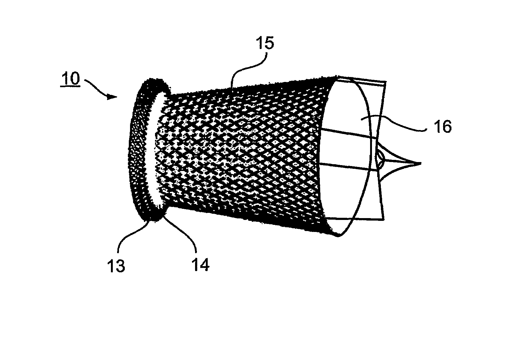
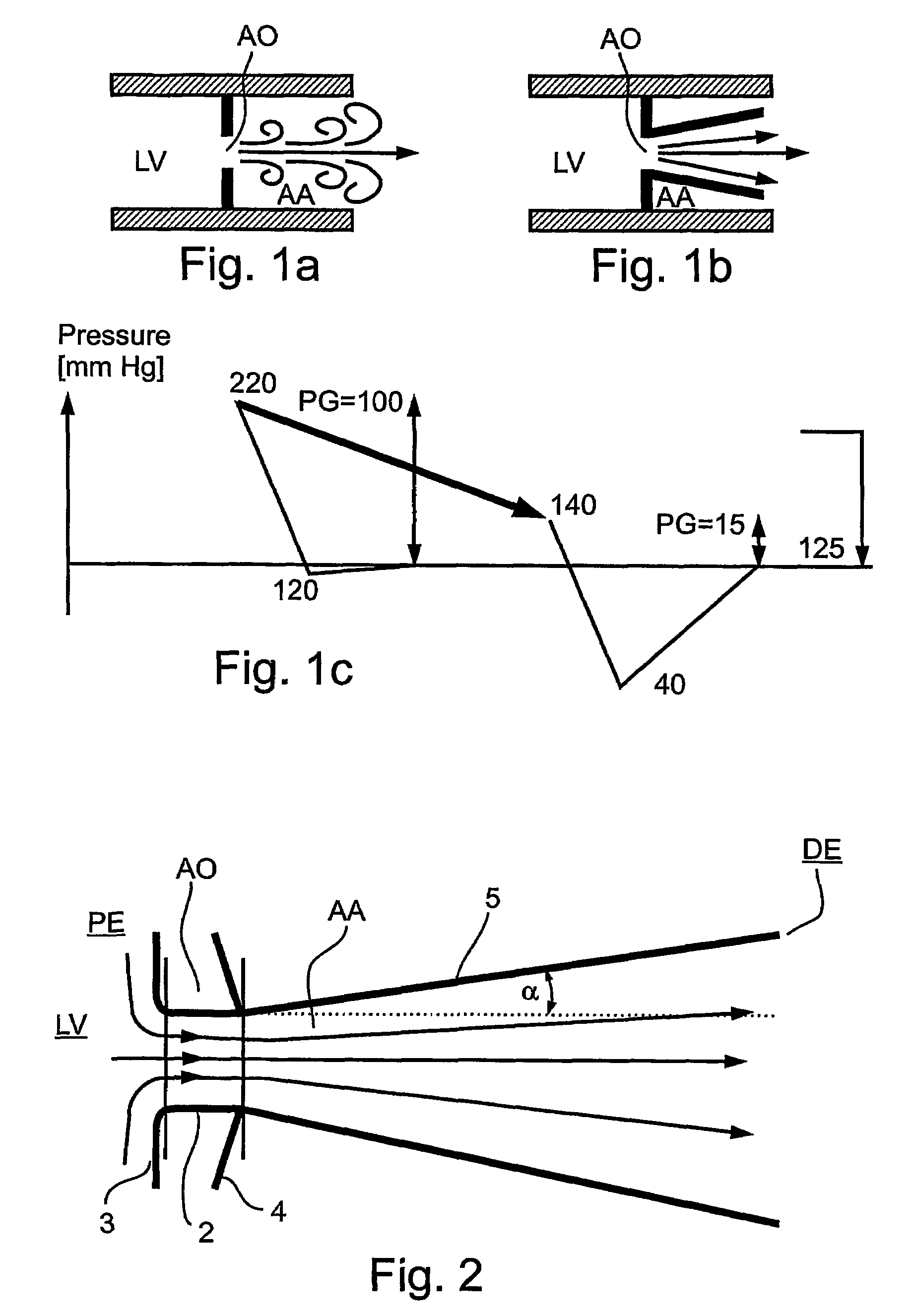
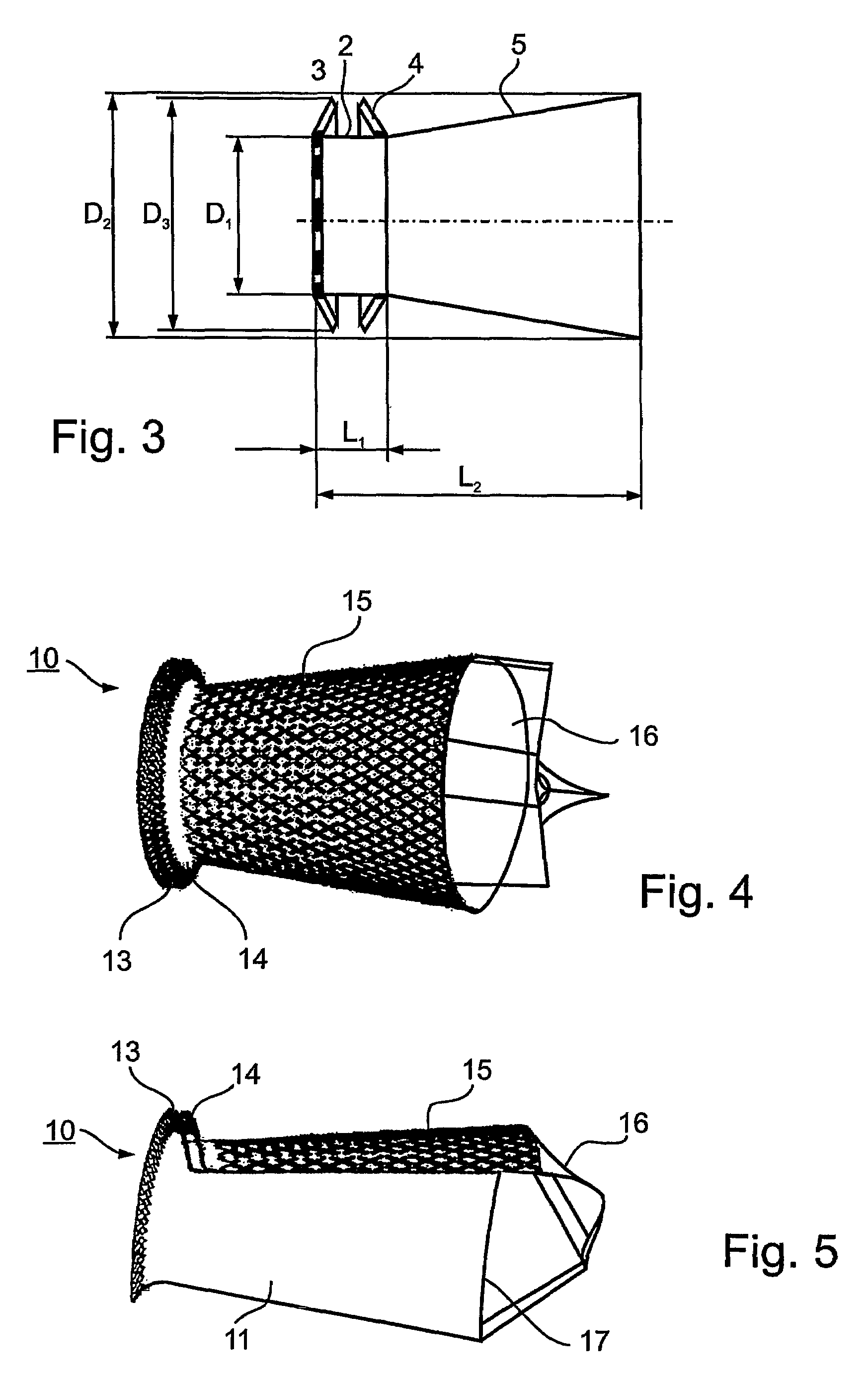
[0039]As noted above, the present invention is primarily directed to implanting a prosthetic device into a diseased aortic valve for use in the treatment of aortic stenosis. This device is designed to aid blood pressure recovery so as to decrease the pressure gradient between the left ventricle and the aorta, thus alleviating the work load placed on the heart. FIG. 2 diagrammatically illustrates one construction of prosthetic device in accordance with the present invention, and FIGS. 1a-1c diagrammatically illustrate the manner in which such a prosthetic device may be used for alleviating the work load placed on the heart by an aortic valve suffering from significant aortic stenosis.

[0040]The principles of flow regulation in the cardiovascular system are quite similar to those in pipeline systems. Aortic pressure and cardiac output are regulated by the baroreceptor-system with its stretch-receptors in the aorta and carotid artery. Any loss of press...


PUM


Abstract

A prosthetic device is provided for treatment of an aortic valve, having a compressed state for transarterial delivery and being expandable to an expanded state for implantation. The device includes an expandable support implantable in the expanded state of the prosthetic device in an aortic annulus, and an inner envelope having an upstream portion that lines the inner surface of the support, and a downstream portion which, when the prosthetic device is in the expanded state, extends into an aorta and defines a diverging conical section having a diameter that gradually increases from an upstream end of the section to a downstream end of the section. The section is configured to produce, during systole, a non-turbulent blood flow into the aorta with pressure recovery at the downstream end of the section. Other embodiments are also described.

Description

[0001]This application claims the benefit of U.S. Provisional Application No. 60 / 485,156 filed Jul. 8, 2003 and incorporates the same by reference.FIELD AND BACKGROUND OF THE INVENTION[0002]The present invention relates to implantable prosthetic devices. The invention is particularly useful in prosthetic devices implantable by transarterial delivery for the treatment of aortic stenosis in the aortic valve of a patient's heart, and the invention is therefore described below with respect to such application. It will be appreciated, however, that the invention could also be used for other treatments, e.g., for aortic regurgitation and other valvular lesions. The invention also relates to methods for implanting such prosthetic devices.[0003]Aortic stenosis is the obstruction of outflow from the left ventricular chamber into the aorta caused by restricted opening of the aortic valve during cardiac contraction. The diminished aortic valve opening area (from normally 3 cm2 to less than 0.5...

Claims


Application Information

Patent Timeline
Patent Type & Authority Patents(United States)
IPC IPC(8): A61F2/24A61FA61F2/06A61F2/86
CPCA61F2/24A61F2/2418A61F2/2436A61F2220/0058A61F2/97A61F2002/068A61F2220/005A61F2/86A61F2/06A61F2/958
Inventor SCHWAMMENTHAL, EHUDTUVAL, YOSSIBENARY, RAPHAEL
Owner MEDTRONIC VENTOR TECH
Why Eureka
Try Eureka