Vehicle-use generator

a generator and vehicle-use technology, applied in the direction of electric generator control, magnetic circuit shape/form/construction, magnetic circuit rotating parts, etc., can solve the problems of slow regulation speed of its generation voltage and difficulty in keeping the generation voltage at the target regulation voltage, so as to improve the output control responsiveness of vehicle-use generators, reduce field current, and suppress the effect of field coil temperature ris

Inactive Publication Date: 2008-09-30
DENSO CORP
View PDF20 Cites 8 Cited by
  • Summary
  • Abstract
  • Description
  • Claims
  • Application Information

AI Technical Summary

Benefits of technology

[0013]According to the one aspect of the invention in which field coils of a vehicle-use generator having the tandem rotor structure are connected in parallel with respect to an excitation current source, it is possible to greatly improve the output control responsiveness of the vehicle-use generator, because the excitation inductance of the entire excitation circuit of the vehicle-use generator can be significantly reduced compared to a conventional case where field coils of a vehicle-use generator are connected in series with respect to an excitation current source, In addition, since it is not necessary to reduce the turn number of each of the field coils, each field coil can have an ampere-turn value (excitation inductance) large enough to generate a required magnetic flux without increasing a field current flowing therethrough.
[0022]According to the another aspect of the invention in which a field coil of a vehicle-use generator is applied with an excitation voltage produced by stepping up an output voltage of a vehicle battery charged by the vehicle-use generator, it is possible to rapidly increase or decrease the field current compared to a conventional case where a field coil is applied with an output voltage of a vehicle battery. Accordingly, according to the another aspect of the invention, the output control responsiveness of a vehicle-use generator can be greatly improved without incurring high cost.

Problems solved by technology

However, such a tandem type vehicle-use generator has a problem in that a regulation speed of its generation voltage is slow, because the excitation circuit of the Lundell type rotor structure in which a field coil having a large number of turns is wound around claw-shaped pole cores exhibits a considerably large inductance, and accordingly exhibits a considerably large excitation time constant.
This makes it difficult to keep the generation voltage at its target regulation voltage by adjusting an excitation current, when a consumption current of an electric load varies rapidly.

Method used


Image

  • Vehicle-use generator
  • Vehicle-use generator
  • Vehicle-use generator

Examples


second embodiment

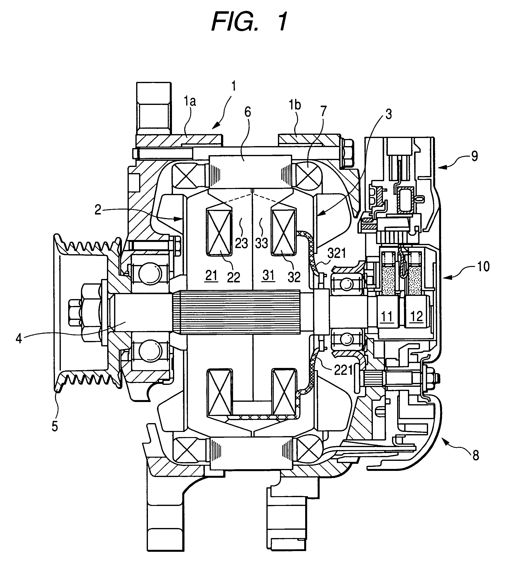
[0053]FIG. 5 is a schematic cross-sectional view of a vehicle-use generator according to a second embodiment of the invention.

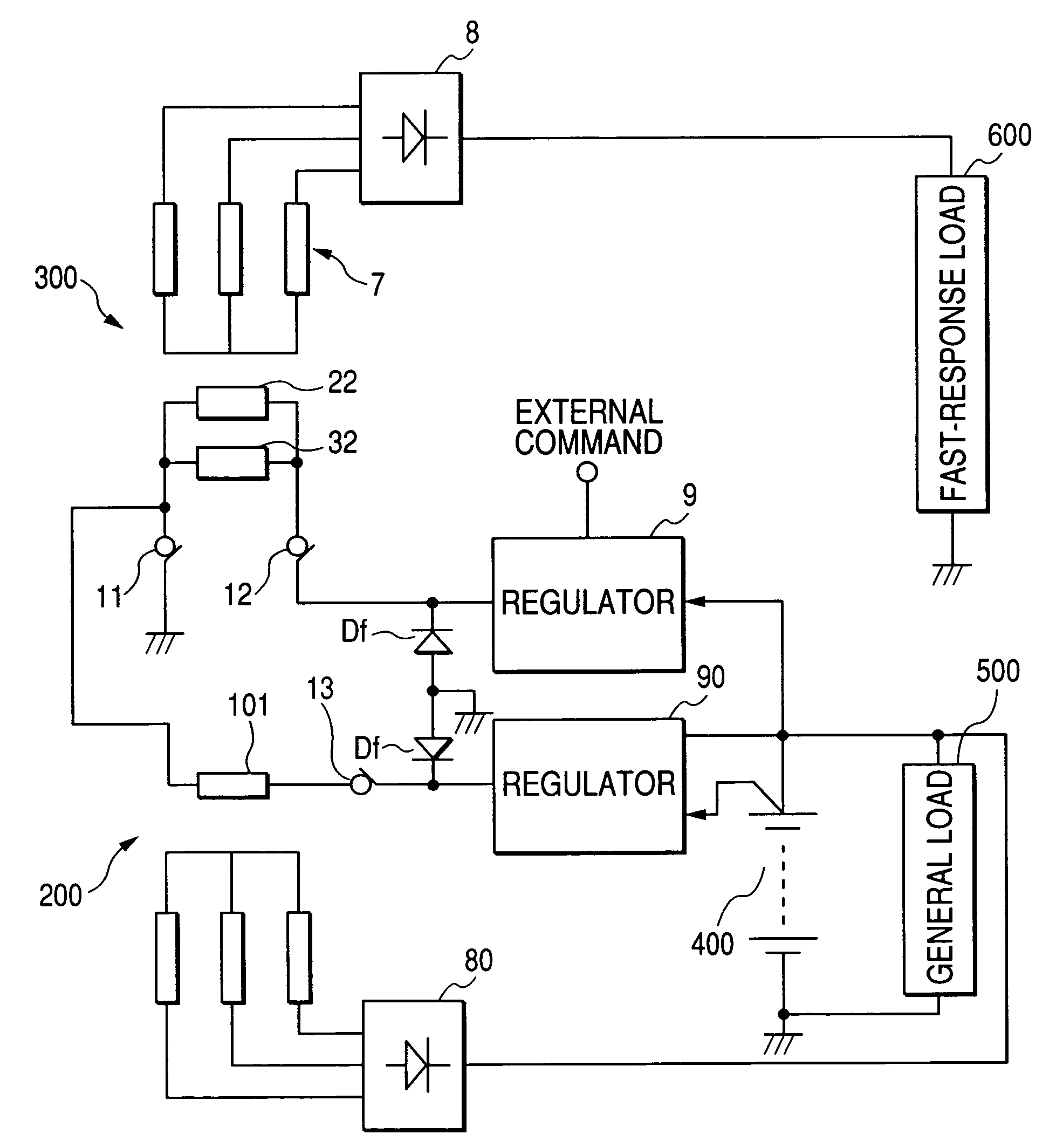
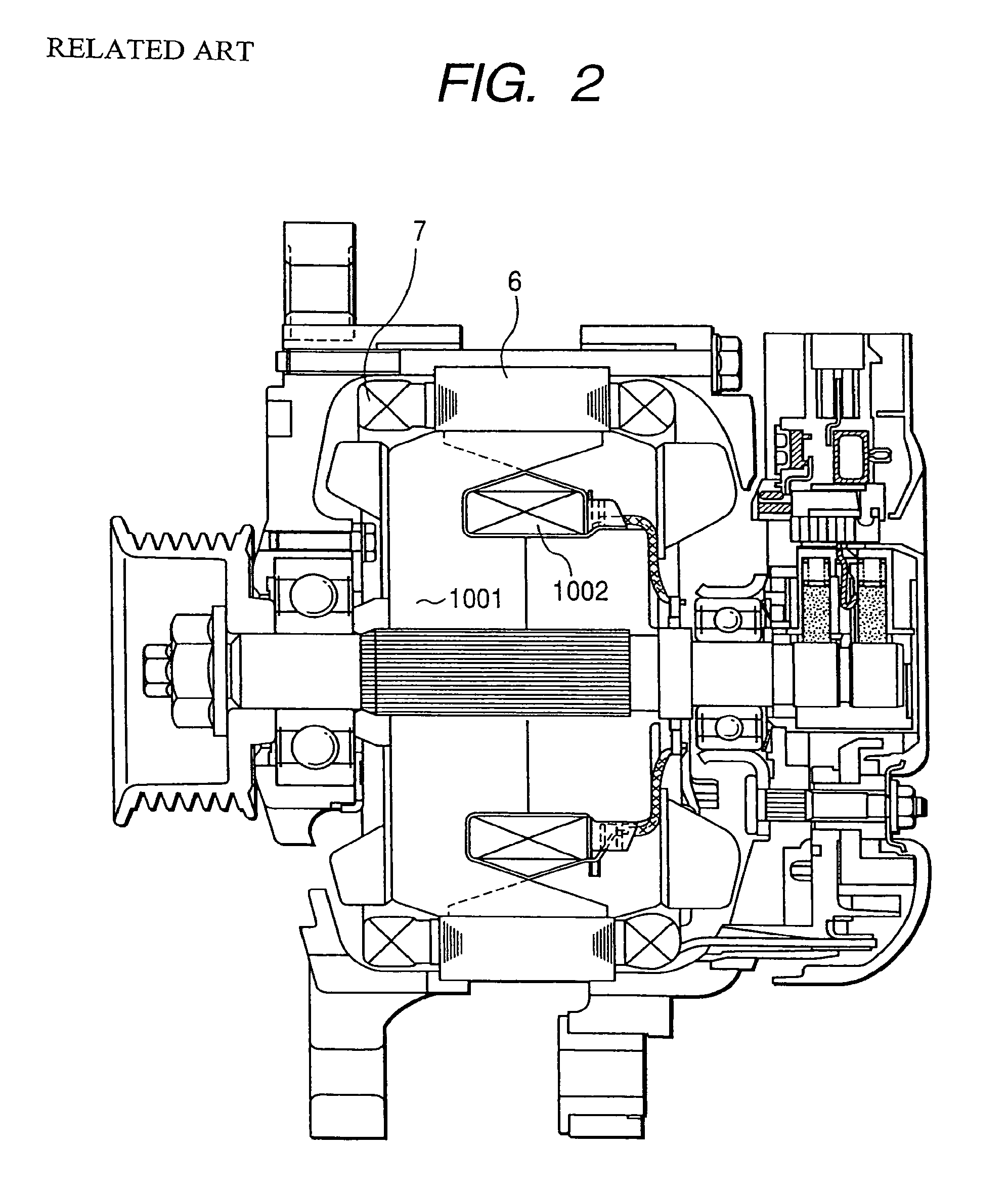
[0054]The second embodiment has a three-throw tandem rotor structure in which another Lundell type rotor core 100 is added to the rotor cores 21, 31 shown in FIG. 1. In FIG. 5, the reference numeral 101 denotes a field coil wound around the Lundell type rotor core 100, 60 denotes a stator core, 70 denotes a stator coil wound around the stator core 60. Here, the stator-rotor pair constituted by the Lundell type rotor cores 21, 31, the field coils 22, 32, the stator core 6, and the stator coil 7 is designated as a first stator-rotor pair 300, and the stator-rotor pair constituted by the Lundell type rotor core 100, the field coil 101, the stator core 60, and the stator coil 70 is designated as a second stator-rotor pair 200.

[0055]FIG. 6 is a circuit diagram showing an electrical structure of the vehicle-use generator of the second embodiment. As shown in this f...

third embodiment

[0057]FIG. 7 is a circuit diagram showing an electrical structure of a vehicle-use generator according to a third embodiment of the invention.

[0058]The third embodiment is different from the first embodiment in that a chopper type DC-DC converter 900 is provided for stepping up the voltage of the battery 400, and the field coils 22, 32 are applied with this stepped up voltage in the third embodiment. The DC-DC converter 900 is constituted by transistors 91, 92, and a reactor 93 for accumulation of magnetic energy.

[0059]The transistors 91, 92 of the DC-DC converter 900 are turned on and off at a certain frequency by the regulator 9. The voltage-step-up ratio of the DC-DC converter 900 is determined by the duty ratios of these transistors. When the transistor 92 is turned on, and the transistor 91 is turned off, magnetic energy is accumulated in the reactor 93. Subsequently, when the transistor 92 is turned off, and the transistor 91 is turned on, the field coils 22, 32 are applied wi...

fourth embodiment

[0061]FIG. 8 is a circuit diagram showing an electrical structure of a vehicle-use generator according to a fourth embodiment of the invention. The fourth embodiment is different from the third embodiment shown in FIG. 7 in that a vibration reduction circuit 2000 and an electric double-layer type smoothing capacitor 3000 having a large capacitance are additionally provided in the fourth embodiment.

[0062]The vibration reduction circuit 2000 is for reducing an engine vibration and a vehicle vibration caused by the engine vibration by controlling the phase of the power generation torque of the vehicle-use generator coupled to the engine through a belt-pulley mechanism which enables torque transmission therebetween. More specifically, the vibration reduction circuit 2000 controls the power generation torque such that the power generation torque and the engine torque vary in opposite phase to each other.

[0063]When the vibration reduction circuit 2000 receives a signal from outside indica...


PUM


Abstract

The vehicle-use generator includes a first rotor core having a first field coil wound therearound, a second rotor core having a second field coil wound therearound, a rotating shaft belt-driven by a vehicle engine, the first and second rotor cores being mounted in tandem on the rotating shaft, a stator core having a stator coil wound therearound, and disposed radially outwardly of the first and second rotor cores so as to form a circumferential gap with the first and second rotor cores. The first and second field coils are connected substantially in parallel to each other when viewed from an external field current supply source supplying field currents to the first and second field coils.

Description

CROSS-REFERENCE TO RELATED APPLICATION[0001]This application is related to Japanese Patent Application No. 2005-263662 filed on Sep. 12, 2005, the contents of which are hereby incorporated by reference.BACKGROUND OF THE INVENTION[0002]1. Field of the Invention[0003]The present invention relates to a vehicle-use generator, and more particularly to a vehicle-use generator including tandem rotor cores each of which has claw-shaped magnetic pole cores around which a field coil is wound.[0004]2. Description of Related Art[0005]There is known a vehicle-use generator having a tandem rotor structure in which two Lundell type rotors are tandem-connected (may be referred as a tandem type vehicle-use generator hereinafter), as disclosed, for example, in Japanese Patent Application Laid-open Nos. 1-157251, 5-137295, and 5-308751. Such a tandem rotor structure makes it possible to provide a compact and low-cost vehicle-use generator capable of outputting two different generation voltages that ca...

Claims


Application Information

Patent Timeline
Patent Type & Authority Patents(United States)
IPC IPC(8): H02K1/22
CPCH02K16/00H02K16/02H02P9/48H02P2101/45H02K19/22
Inventor MUKAI, TAKUZOUKUSASE, SHIN
Owner DENSO CORP
Why Eureka
Try Eureka