
Overvoltage protection of a frequency converter

a frequency converter and overvoltage protection technology, applied in power conversion systems, emergency protection arrangements for limiting excess voltage/current, emergency protection arrangements for automatic disconnection, etc., can solve the problems of occupying a lot of space, and increasing the cost of the device, so as to achieve reliable protection and economical cost

Inactive Publication Date: 2008-09-30
VACON OY
View PDF16 Cites 18 Cited by
  • Summary
  • Abstract
  • Description
  • Claims
  • Application Information

AI Technical Summary

Benefits of technology

[0013]The object of the present invention is to overcome the drawbacks of prior art and to create an overvoltage switching system for the intermediate circuit of a PWM-frequency converter that allows reliable protection to be achieved using components of economical cost.
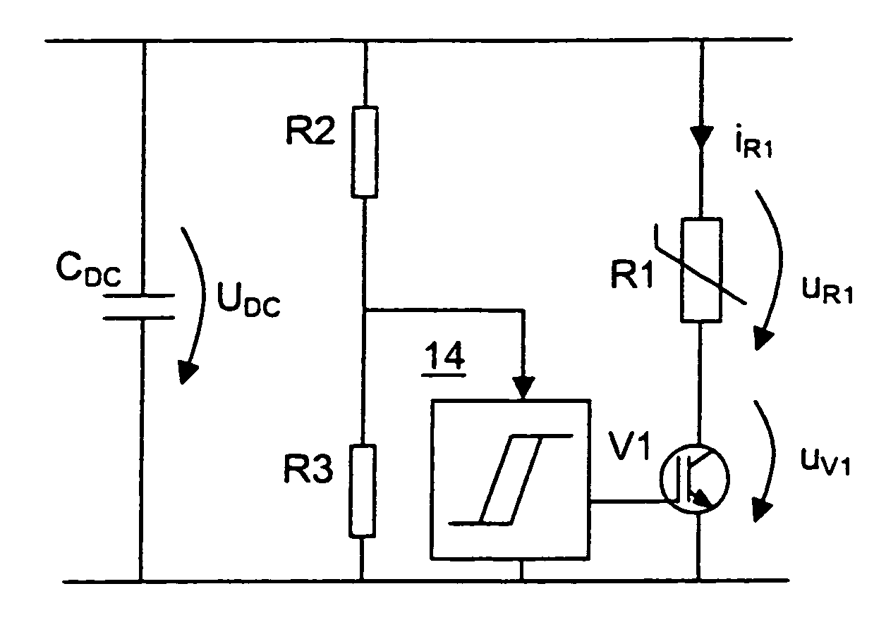
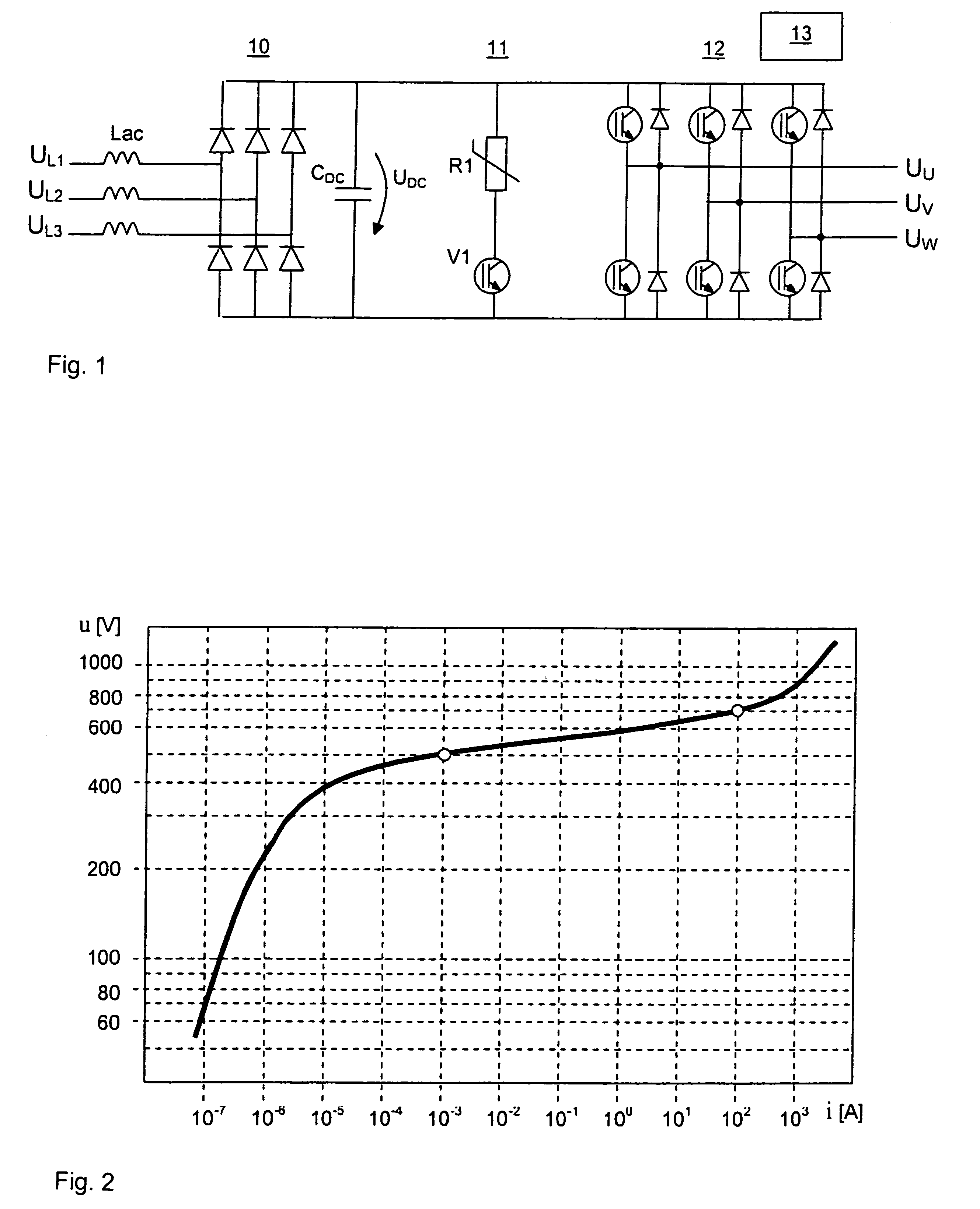
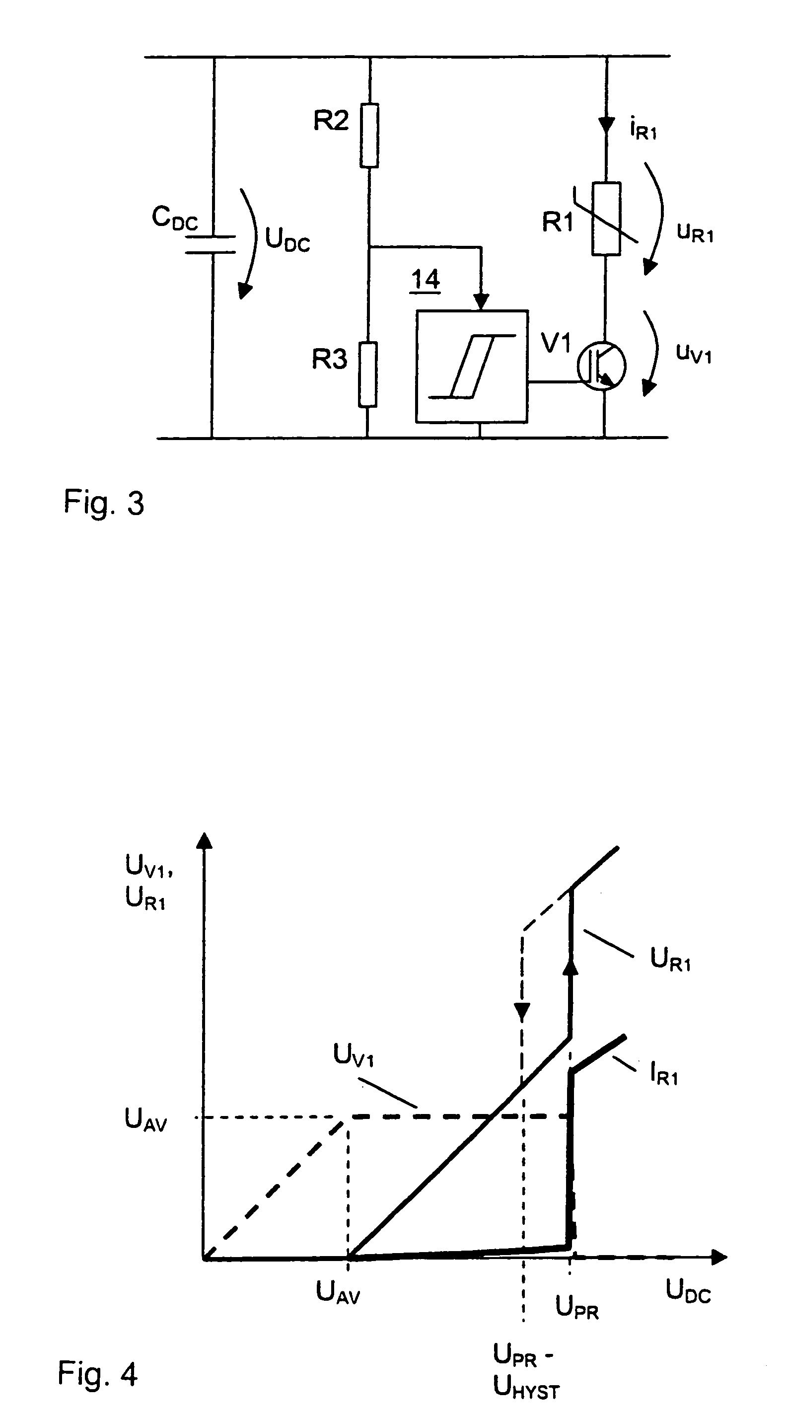
[0014]According to the invention, overvoltage protection is implemented using a series connection of a varistor and a low-voltage power semiconductor switch, wherein the voltage rating of the power semiconductor switch is lower than the normal operating level of the intermediate circuit. In this way, reliable overvoltage protection of the intermediate circuit of a frequency converter provided with a small intermediate-circuit capacitor is achieved, based on well known, small-sized components of economical cost that have proved to be reliable.

Problems solved by technology

The solution has the drawback of requiring additional components in the circuit, e.g. an electrolytic capacitor, which take up plenty of space and increase the costs of the device.
A drawback with this solution are the chopper components, which increase the costs of the device and take up plenty of space.
However, a power Zener is a very expensive component.

Method used


Image

  • Overvoltage protection of a frequency converter
  • Overvoltage protection of a frequency converter
  • Overvoltage protection of a frequency converter

Examples


Embodiment Construction

[0021]FIG. 1 presents a three-phase voltage-controlled PWM-frequency converter comprising a mains bridge (rectifier) 10 for rectifying the three-phase alternating voltage of a supply network, consisting of phase voltages UL1, UL2, UL3, to produce an intermediate-circuit direct voltage UDC and a load bridge (inverter) 12 for inverting the intermediate-circuit direct voltage to produce a three-phase alternating voltage of variable frequency having phase voltages UU, UV, UW when power is flowing from the network to the load. The frequency converter may feed e.g. a three-phase alternating-current motor. The load bridge 12 is a full-wave bridge with a control unit 13 controlling the phase switches of each phase via pulse-width modulation. ‘Phase switch’ refers to the switch formed by the semiconductor switches of the upper and lower branches of a phase together, with a diode connected in inverse-parallel with each power semiconductor switch. The mains bridge 10 is an uncontrolled full-wa...


PUM


Abstract

An overvoltage protection system for the intermediate circuit of frequency converter, said frequency converter being a voltage-controlled PWM-frequency converter comprising an uncontrolled mains bridge (10) to be connected to an alternating-current source (UL1, UL2, UL3), a direct-voltage intermediate circuit and a controlled load bridge (12) for producing a multi-phase alternating voltage (UU, UV, UW) of variable frequency, wherein the direct-voltage circuit of the frequency converter contains a low-capacitance direct-voltage capacitor, the mains bridge (10) being connected to the load bridge (12) directly without a high-capacitance direct-voltage capacitor serving as an intermediate energy storage, and which overvoltage protection system contains a varistor (R1). The overvoltage protection system consists of a series connection of the varistor (R1) and a semiconductor switch (V1), said series connection being connected in parallel with the direct-voltage capacitor, which semiconductor switch has a voltage rating lower than the normal operating level of the direct-voltage intermediate circuit.

Description

BACKGROUND OF THE INVENTION [0001]1. Field of the Invention[0002]The present invention relates to an overvoltage protection system for the intermediate circuit of a frequency converter. In particular, the invention concerns an overvoltage protection system for a frequency converter provided with a small intermediate-circuit capacitor and controlled by pulse-width modulation (PWM).[0003]2. Discussion of the Background[0004]A PWM frequency converter provided with a small intermediate circuit capacitor is disclosed e.g. in specification U.S. Pat. No. B2-6,801,441. This specification describes a multi-phase voltage-controlled PWM frequency converter comprising a control unit, an uncontrolled mains bridge to be connected to a multi-phase alternating-current source, a direct-voltage intermediate circuit and a controlled load bridge for feeding a variable-frequency multi-phase alternating voltage to a multi-phase load, in which frequency converter the mains bridge is connected to the load ...

Claims


Application Information

Patent Timeline
Patent Type & Authority Patents(United States)
IPC IPC(8): H02H3/22H02M1/00H02M1/32H02M5/458
CPCH02M5/458H02M1/32
Inventor KOMULAINEN, RISTOBJORKGREN, TRYGVE
Owner VACON OY
Learn More