Motor vehicle and control method of internal combustion engine

a technology of internal combustion engine and control method, which is applied in the direction of engines, machines/engines, propulsion parts, etc., can solve the problems of increasing the temperature of cooling water in the engine for a relative long time, worsening the fuel economy, and measuring the acceleration of the warm-up of the engine, so as to achieve the effect of improving the fuel economy

Inactive Publication Date: 2008-09-30
TOYOTA JIDOSHA KK
View PDF21 Cites 14 Cited by
  • Summary
  • Abstract
  • Description
  • Claims
  • Application Information

AI Technical Summary

Benefits of technology

[0005]In the hybrid vehicle of the proposed arrangement for utilizing the heat produced by the engine to heat the passenger compartment, the engine restarts to produce the heat required for heating the passenger compartment, even in the motor drive mode using the power of the electric motor alone for driving. In the low temperature state, however, a relatively long time is required to increase the temperature of cooling water in the engine. This worsens the fuel economy.
[0006]The short purge time of the evaporated fuel adsorbed in the canister improves the fuel economy in the low outside air temperature condition, but this measure does not take into account acceleration of the warm-up of the engine.
[0007]In a motor vehicle of the invention and a control method of an internal combustion engine, there is a need of improving fuel economy. In the motor vehicle of the invention and the control method of the internal combustion engine, there is also a need of accelerating warm-up of the internal combustion engine.

Problems solved by technology

In the low temperature state, however, a relatively long time is required to increase the temperature of cooling water in the engine.
This worsens the fuel economy.
The short purge time of the evaporated fuel adsorbed in the canister improves the fuel economy in the low outside air temperature condition, but this measure does not take into account acceleration of the warm-up of the engine.

Method used


Image

  • Motor vehicle and control method of internal combustion engine
  • Motor vehicle and control method of internal combustion engine
  • Motor vehicle and control method of internal combustion engine

Examples


Embodiment Construction

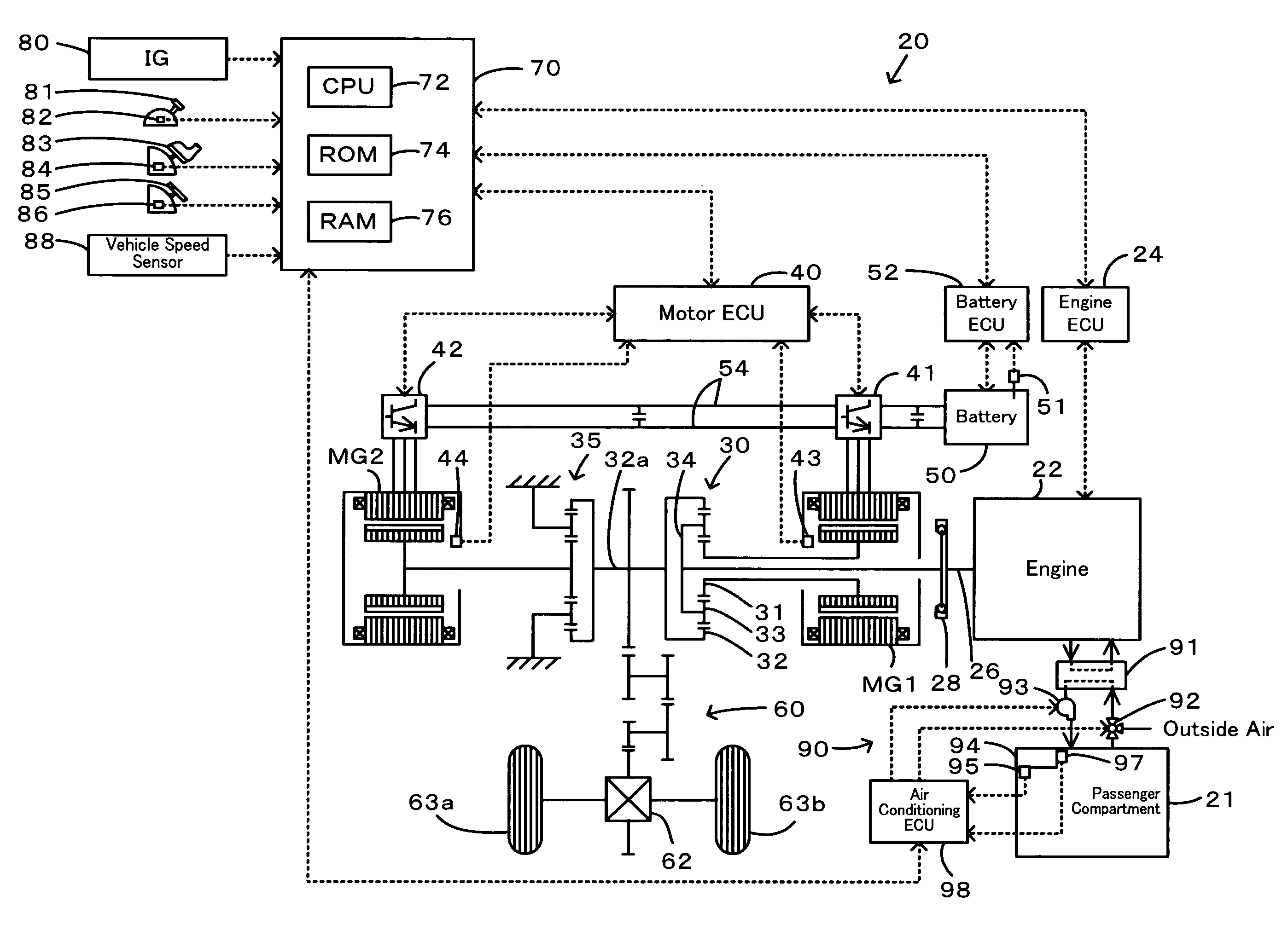
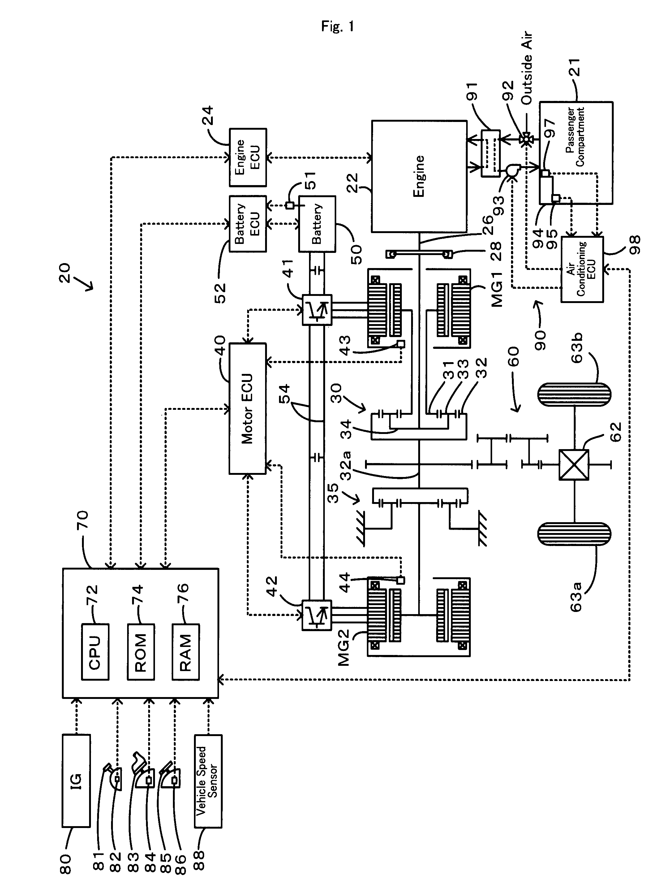
[0031]One mode of carrying out the invention is discussed below as a preferred embodiment with reference to the accompanied drawings. FIG. 1 schematically illustrates the configuration of a hybrid vehicle 20 in one embodiment of the invention. As illustrated, the hybrid vehicle 20 of the embodiment includes an engine 22, a three shaft-type power distribution integration mechanism 30 that is linked to a crankshaft 26 or an output shaft of the engine 22 via a damper 28, a motor MG1 that is linked to the power distribution integration mechanism 30 and has power generation capability, a reduction gear 35 that is attached to a ring gear shaft 32a or a driveshaft linked to the power distribution integration mechanism 30, a motor MG2 that is linked to the reduction gear 35, an air conditioning system 90 that conditions the air in a passenger compartment 21, and a hybrid electronic control unit 70 that controls the operations of the whole hybrid vehicle 20.

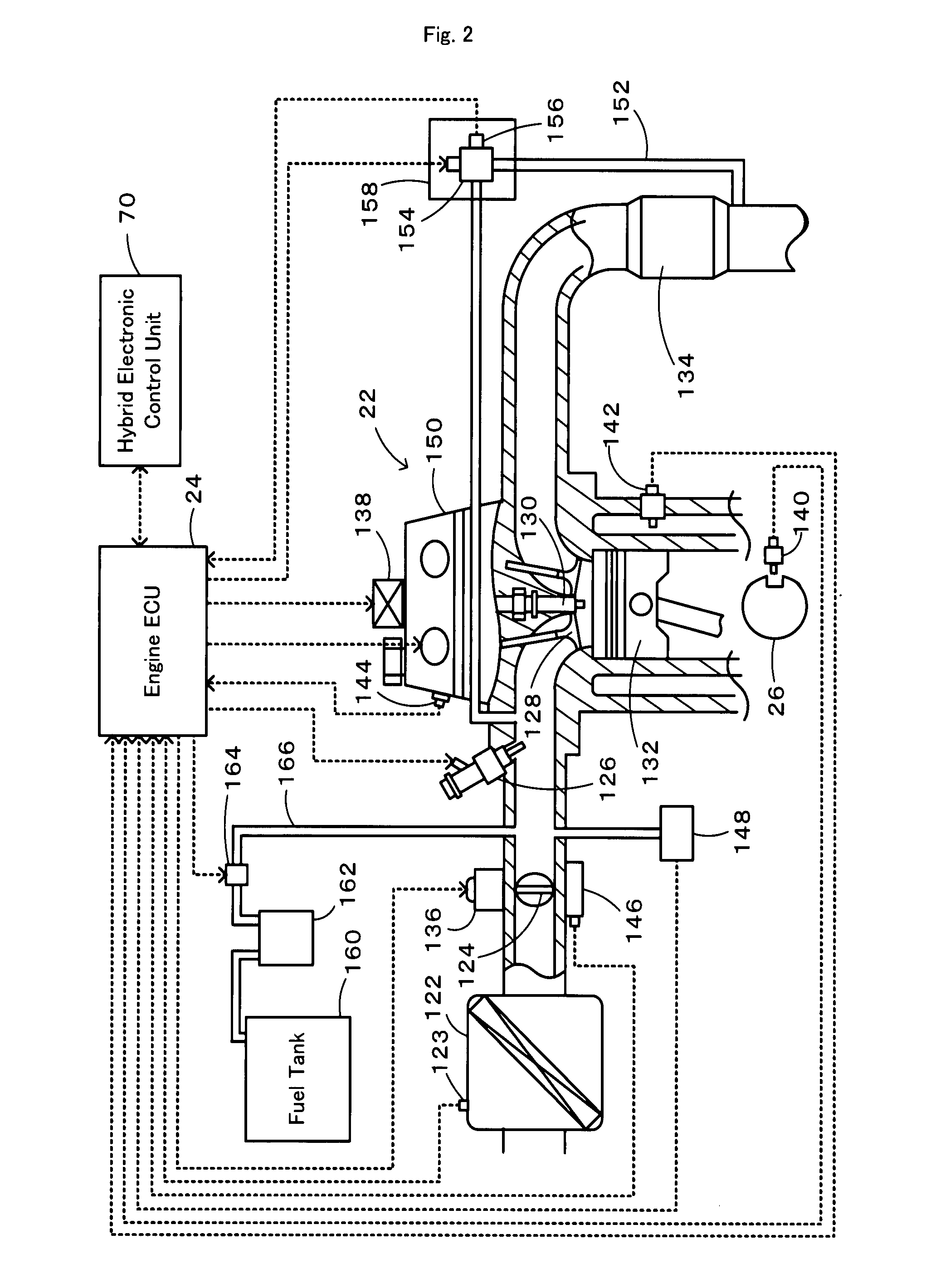
[0032]The engine 22 is an internal...


PUM


Abstract

In a motor vehicle, when an intake air temperature Ta is not lower than a preset reference temperature Tref, warm-up drive control selectively uses an evaporated fuel processing acceleration operation curve, which gives a high level of a negative pressure in an intake manifold, to set a target drive point of an engine and controls the operation of the engine. This ensures good emission of the engine. When the intake air temperature Ta is lower than the preset reference temperature Tref and when the setting of a heating demand Hq requires heating, on the other hand, the warm-up drive control increases an EGR quantity from an ordinary level and switches over an operation mode of a cooling system for the engine to a warm-up circulation mode for making the flow of a cooling medium bypass a radiator.

Description

[0001]This is a 371 national phase application of PCT / JP2004 / 014021 filed 17 Sep. 2004, the content of which is incorporated herein by reference.TECHNICAL FIELD[0002]The present invention relates to a motor vehicle and a control method of an internal combustion engine mounted on the motor vehicle.BACKGROUND ART[0003]A hybrid vehicle of one proposed arrangement specifies the timing for a restart of an engine, based on the inner temperature of a passenger compartment, the set temperature of an air conditioner in the passenger compartment, and the temperature of cooling water in an engine (see, for example, Japanese Patent Laid-Open Gazette No. H09-233601). When the temperature difference between the inner temperature of the passenger compartment and the set temperature of the air conditioner in the passenger compartment is not less than a preset reference value, this hybrid vehicle restarts the engine even in a vehicle stop state or in a motor drive mode using the power of an electric...

Claims


Application Information

Patent Timeline
Patent Type & Authority Patents(United States)
IPC IPC(8): F02D28/00G06F7/70
CPCB60K6/445B60W10/06B60W10/24B60W30/192F02D41/003F02D41/0055F02D41/068F02M25/0818F02M25/0827Y02T10/47B60W20/00B60W2510/0671B60W2510/0676F02D41/021F02D2200/0406F02D2200/0414F02D2250/41Y02T10/6239B60L2240/445B60L1/003B60L1/02B60L2240/34B60L2240/44B60L2240/662B60L2260/22B60L2260/26B60L2260/28B60L50/16B60L50/61Y02T10/40Y02T10/62Y02T10/70Y02T10/7072Y02T10/72Y02T90/16
Inventor KAITA, KEIJI
Owner TOYOTA JIDOSHA KK
Why Eureka
Try Eureka