Diesel combustion system with re-entrant piston bowl

a technology of re-entrant pistons and combustion systems, which is applied in the direction of combustion engines, internal combustion piston engines, machines/engines, etc., can solve the problems of increasing fuel consumption, increasing soot formation, and difficult control of certain exhaust emission components, so as to reduce fuel consumption, increase soot or particulate emissions, and constant nox emission of engines

Active Publication Date: 2008-10-07
GE GLOBAL SOURCING LLC
View PDF6 Cites 23 Cited by
  • Summary
  • Abstract
  • Description
  • Claims
  • Application Information

AI Technical Summary

Benefits of technology

[0011]It is an advantage of the diesel combustion system according to the present invention that fuel consumption may be reduced without increasing soot or particulate emissions, while at the same time maintaining constant NOx emissions of an engine.
[0012]It is another advantage of the present diesel combustion system that particulate matter may be maintained at a constant or even reduced level, as compared with existing engines, but with superior fuel economy, and without increasing NOx emissions.

Problems solved by technology

With compression ignition engines, commonly called ‘diesel’ engines, certain exhaust emission components, including oxides of nitrogen (NOx) and soot, are more difficult to control.
Moreover, alterations in engine operating parameters tending to reduce the fixation of nitrogen also generally tend to increase the amount of soot formed during the combustion process.
This usually has the unfortunate effect of increasing fuel consumption.
This, however, can have the unfortunate effect of increasing soot produced by the engine.
This type of flow results in early nitrogen fixation, as well as momentum loss, which limits the recirculation of partially burned fuel and combustion products into the hotter zone of the cylinder, particularly in view of the peripheral exit angle, which is shown at II as being less than 90°, and which is not optimized to redirect and re-entrain burnt material into the hottest part of the combustion chamber.

Method used


Image

  • Diesel combustion system with re-entrant piston bowl
  • Diesel combustion system with re-entrant piston bowl
  • Diesel combustion system with re-entrant piston bowl

Examples


Embodiment Construction

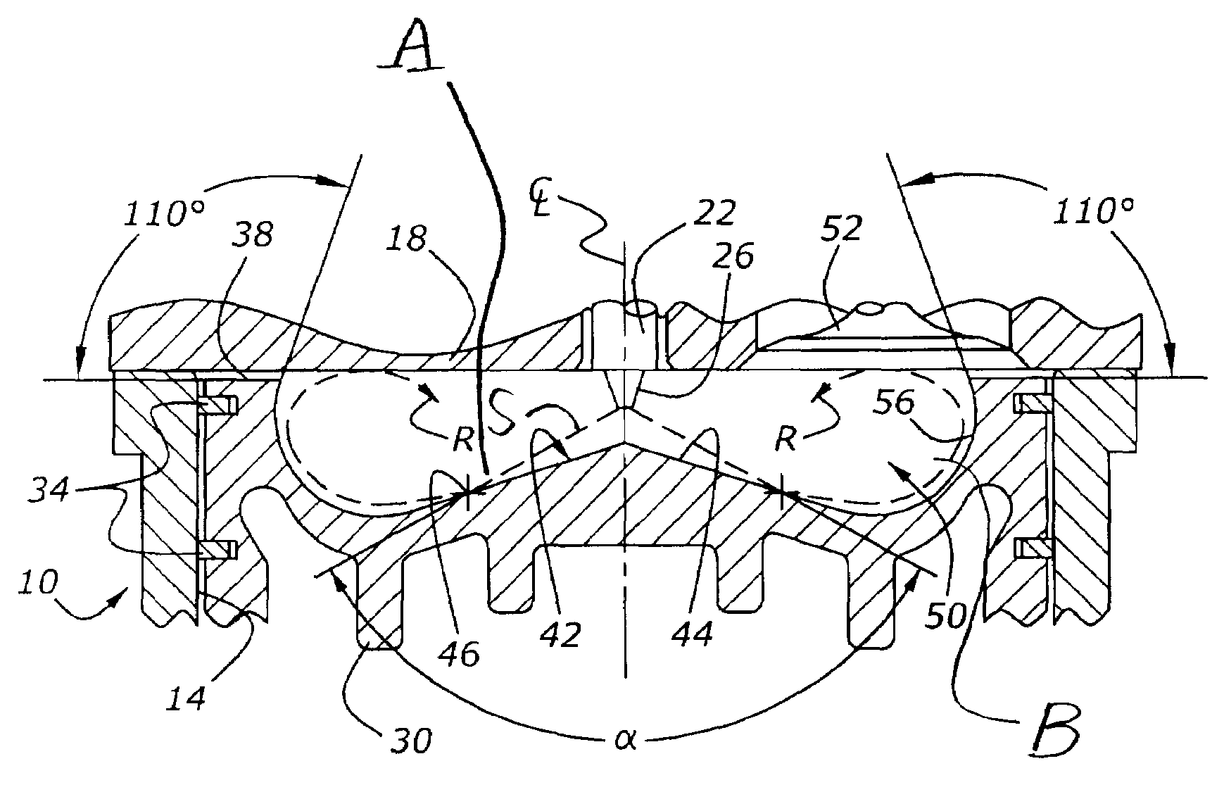
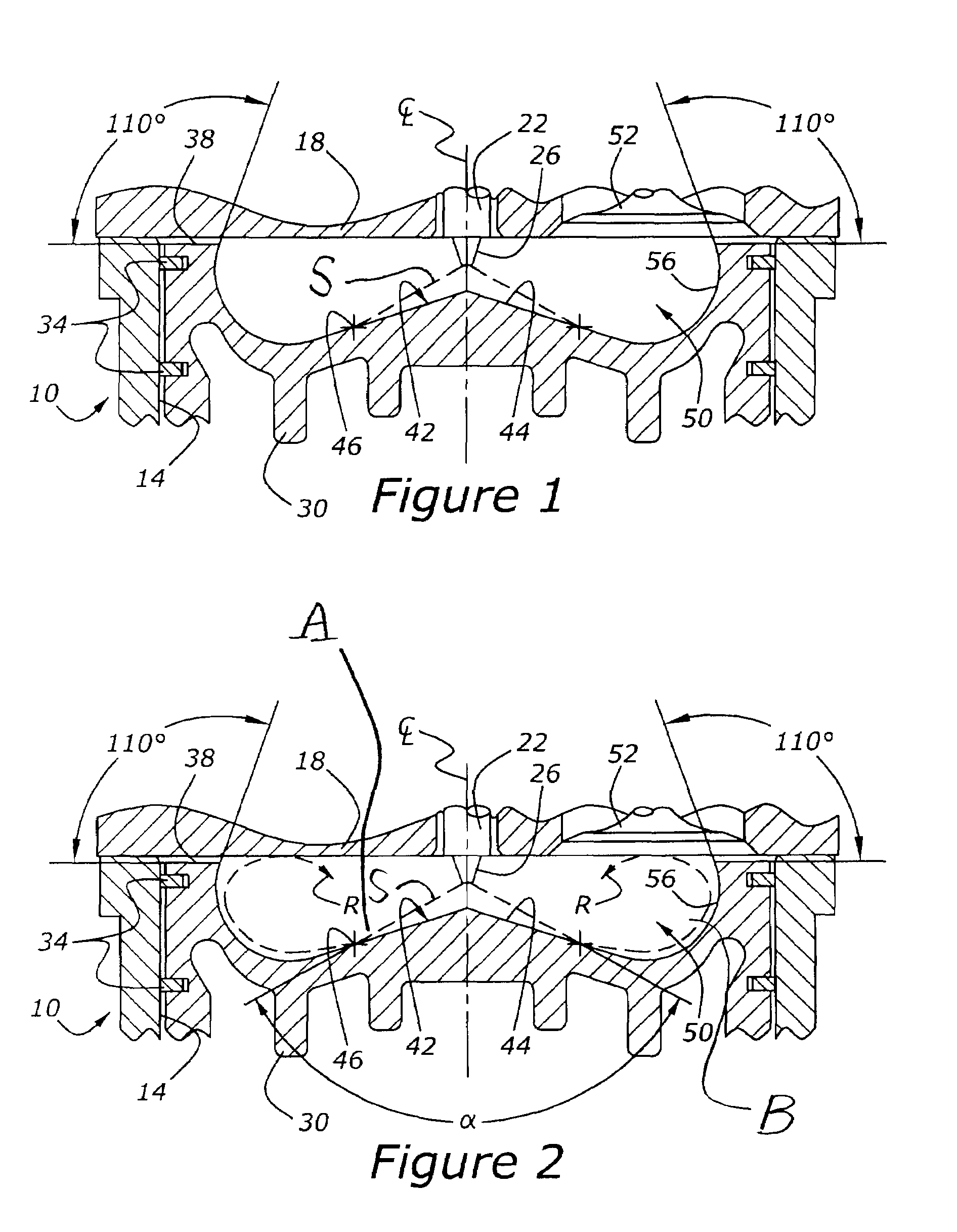
[0017]As shown in FIG. 1, engine 10 has a power cylinder, 14, which is closed by cylinder head 18. Piston 30 is slidably mounted within cylinder 14. Piston 30 has a number of piston rings, 34. Crown 38 of piston 30 has a bowl, 42, formed therein. Bowl 42 has a floor portion, 44, with a midland portion of the floor being identified at 46. The included angle of the apex at the center of bowl 42 is preferably in the range of 140°-150°.

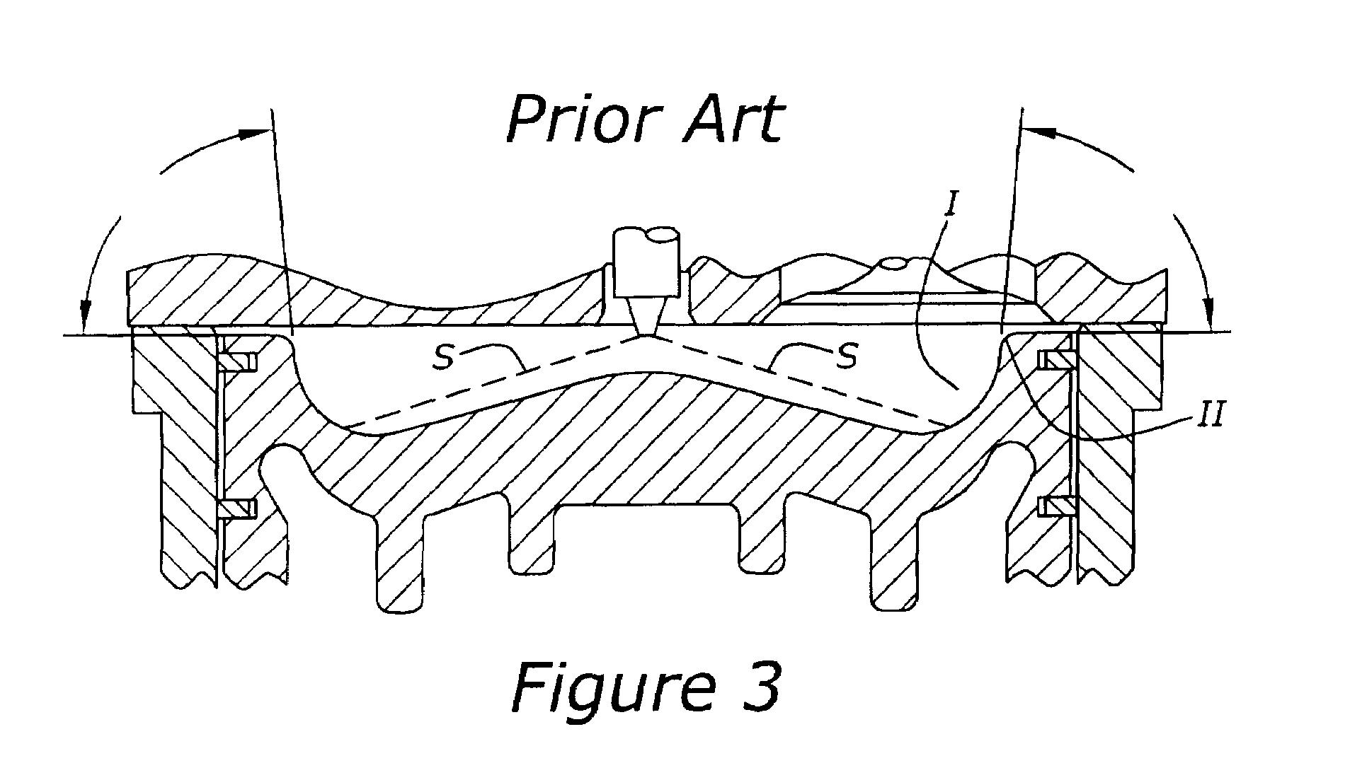
[0018]FIG. 1 also shows a fuel injector, 22, having a nozzle, 26. Fuel injector 22 sprays fuel into combustion chamber 50, which is defined by piston 30 and cylinder head 18. As shown in FIGS. 1 and 2, fuel leaving nozzle 26 in spray S impinges upon the midland portion, 46, of piston bowl 42 and then flows to the outer periphery of bowl 42 before recirculating to middle region R of combustion chamber 50 (FIG. 2). Region R is defined by bowl 42 and cylinder head 18. Cylinder head 18 also includes at least two poppet valves, 52 (one is shown), for admitting...


PUM


Abstract

A diesel combustion system with a re-entrant piston bowl utilizes momentum interaction with the bowl at multiple locations to cause recirculation of the partially burned fuel and combustion products in a toroidal flow so as to consume soot formed during an earlier portion of the combustion process, while reducing the formation of NOx and improving fuel efficiency of the engine.

Description

CROSS REFERENCE TO RELATED APPLICATIONS[0001]None.BACKGROUND OF THE INVENTION[0002]1. Field of the Invention[0003]The subject matter disclosed herein relates to a diesel combustion system including an injector for furnishing fuel directly to the combustion chamber of an engine, as well as to a piston bowl with a floor which interacts with the fuel spray.[0004]2. Discussion of the Prior Art[0005]Designers of internal combustion engines have been confronted with ever more stringent requirements relating to fuel economy and exhaust emissions. With compression ignition engines, commonly called ‘diesel’ engines, certain exhaust emission components, including oxides of nitrogen (NOx) and soot, are more difficult to control. Moreover, alterations in engine operating parameters tending to reduce the fixation of nitrogen also generally tend to increase the amount of soot formed during the combustion process. Presently, NOx and soot are being controlled ever more tightly, and there is a need ...

Claims


Application Information

Patent Timeline
Patent Type & Authority Patents(United States)
IPC IPC(8): F02B19/14F02B7/02F02B1/14
CPCF02B23/0669F02B23/0672Y02T10/125Y02T10/12
Inventor GLENN, WILLIAM D.PRIMUS, ROY J.TAMMA, BHASKARVANETTA, MICHAEL
Owner GE GLOBAL SOURCING LLC
Why Eureka
Try Eureka