Sheet delivery apparatus
a technology of sheet metal and cylinder, which is applied in the directions of transportation and packaging, thin material handling, and article delivery, etc., can solve the problem of continuous periodic sound, and achieve the effect of maintaining discharge efficiency and suppressing nois
- Summary
- Abstract
- Description
- Claims
- Application Information
AI Technical Summary
Benefits of technology
Problems solved by technology
Method used
Image
Examples
first embodiment
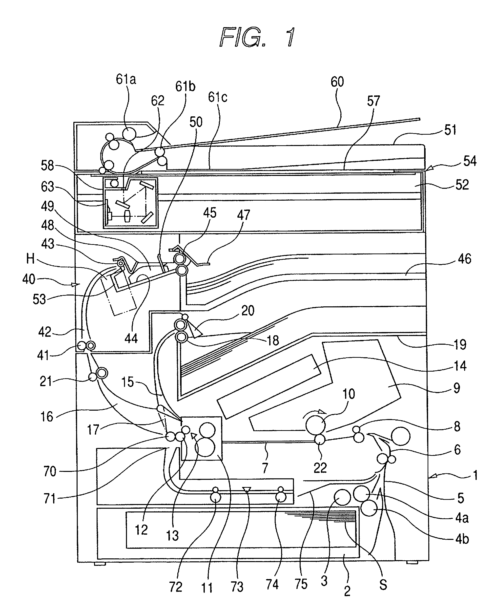
[0028]FIG. 1 shows an image forming apparatus provided with a sheet delivery apparatus to which the present invention has been applied. The image forming apparatus shown in FIG. 1 is an image forming apparatus adopting an electrophotographic system. FIG. 1 is a schematic diagram equivalent to a vertical cross-sectional view in which the image forming apparatus is viewed from a front side, that is, a side on which a user exists at the time of operation of the image forming apparatus. Note that as examples of the image forming apparatus to which the present invention is applicable, it is possible to cite a printer, a copying machine, a facsimile, or a composite machine integrating their functions.
[0029]The image forming apparatus shown in FIG. 1 includes an image forming portion 1, a sheet process portion (sheet process apparatus) 40 disposed above the image forming portion 1, and an image reading portion 54 disposed above the sheet process portion 40.
[0030]In the image forming portio...
second embodiment
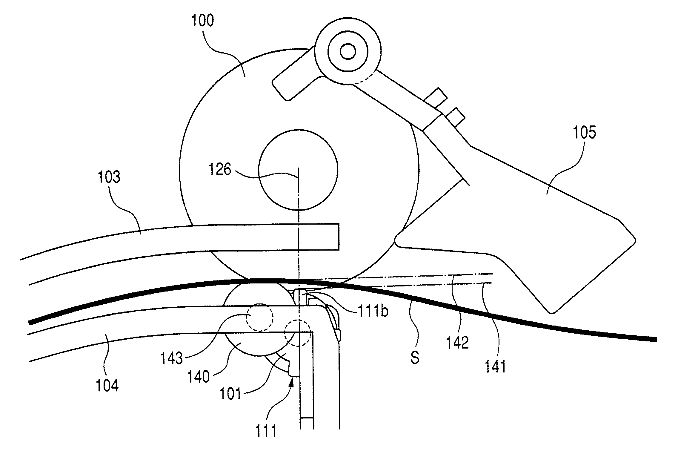
[0059]FIG. 11 shows a second embodiment of the present invention. FIG. 11 is an enlarged view in which the vicinity of a roller 101 is viewed from a front side. This embodiment differs from the first embodiment described above in that guide rollers 140 are disposed in place of the ribs 120 of the first embodiment as the guide portions. Note that other constructions are the same, so the description thereof will be omitted.
[0060]As shown in FIG. 11, the guide rollers 140 have rotation centers 143 on an upstream side with respect to a rotation center of the roller 101. Also, the guide rollers 140 are constructed so that the heights of their peripheral surfaces do not exceed a line 141 corresponding to peripheral surfaces of projection portions 111b on a line 126. Further, the rotation centers 143 are fixed to a transport lower guide 104. Still further, the guide rollers 140 make smooth driven rotation by friction with each sheet S that is transported. With this construction, during the...
third embodiment
[0061]FIG. 13 shows a third embodiment of the present invention. FIG. 13 is an enlarged view in which the vicinity of a roller 101 is viewed from a front side. This embodiment differs from the first and second embodiments described above in that rocking ribs (rocking member) 150 are disposed in place of the ribs 120 and the guide rollers 140 as shown in FIG. 13. Note that other constructions are the same as those of the first embodiment, so the description thereof will be omitted.
[0062]In FIG. 13, the rocking ribs 150 rock about fulcrums 151 in a direction indicated by the arrow 152. The fulcrums 151 are rotatably supported by a transport lower guide 104. On the other hand, downstream sides in a transport direction of the rocking ribs 150 are fitted to the roller 101 through long holes 153 that are long in the sheet transport direction. The roller 101 and the rocking ribs 150 operate in an interlocked manner. Therefore, a relative relation between a line 154 of projection portions 1...
PUM
 Abstract
Description
Claims
Application Information
 - R&D
- Intellectual Property
- Life Sciences
- Materials
- Tech Scout
- Unparalleled Data Quality
- Higher Quality Content
- 60% Fewer Hallucinations
Browse by: Latest US Patents, China's latest patents, Technical Efficacy Thesaurus, Application Domain, Technology Topic, Popular Technical Reports.
© 2025 PatSnap. All rights reserved.Legal|Privacy policy|Modern Slavery Act Transparency Statement|Sitemap|About US| Contact US: help@patsnap.com


