Gas diffusion layer for an electrochemical cell

a technology of electrochemical cells and diffusion layers, applied in the field of electrochemical cells, can solve problems such as the substitution of one problem for another, and achieve the effect of preventing substantial distortion of the membrane electrode assembly

Active Publication Date: 2008-10-07
HYDROGENICS CORP
View PDF19 Cites 15 Cited by
  • Summary
  • Abstract
  • Description
  • Claims
  • Application Information

AI Technical Summary

Benefits of technology

[0007]In accordance with a second aspect of the present invention, there is provided a method of impeding leakage of process fluids from an electrochemical cell having a membrane electrode assembly, a first reactant flow field plate for providing a first reactant flow field disposed on one side of the membrane electrode assembly, a seal disposed between the first reactant flow field plate and the membrane electrode assembly for impeding leakage of process fluids of the electrochemical cell, and a second reactant flow field p...

Problems solved by technology

However, these efforts have been focused on design changes of reactant flow field plates, which are complicated and exp...

Method used


Image

  • Gas diffusion layer for an electrochemical cell
  • Gas diffusion layer for an electrochemical cell
  • Gas diffusion layer for an electrochemical cell

Examples


first embodiment

[0035]FIGS. 4 and 5 show a gas diffusion layer 300 according to the present invention. As is known to those skilled in the art, the gas diffusion layer 300 is made of porous materials, for example, Carbon Felts, paper and cloth, allowing fluids to pass therethrough. When used in electrolyzer cells, a typical material is sintered metal. The present gas diffusion layer 300 is provided with a central portion 310 and an edge portion 320 having reduced thickness. One side 340 of the gas diffusion layer 300 is flat and the other side 330 has a step 325 around the central portion 310.

[0036]Referring to FIG. 6, there is illustrated in a schematic sectional view an electrochemical cell stack incorporating first and second gas diffusion layers 300 and 300′. For clarity, analogous elements between the electrochemical cell stacks of FIGS. 3 and 6 are denoted by the same numerals. As can be seen in FIG. 6, the first and second gas diffusion layers 300 and 300′ are respectively disposed between a...

third embodiment

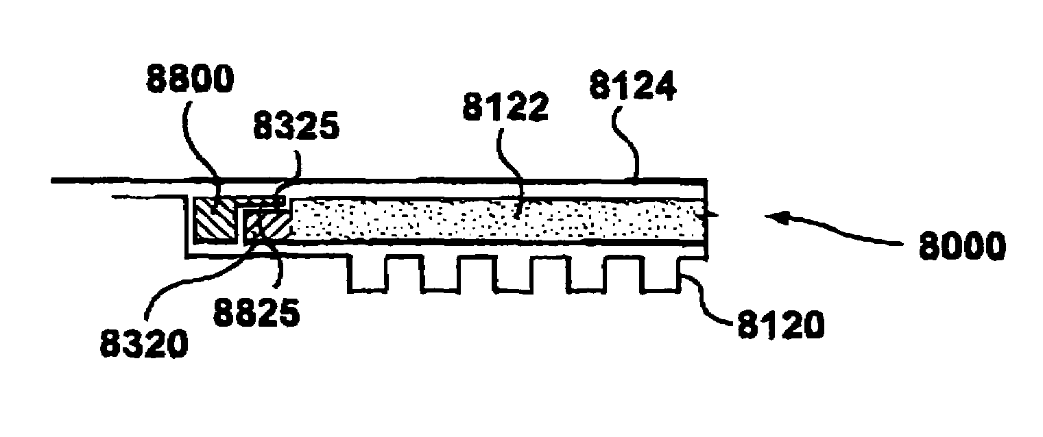
[0039]Referring to FIG. 8, there is illustrated in a schematic sectional view, an electrochemical cell stack 2(000 comprising a gas diffusion layer 2122 in accordance with the invention. For clarity, analogous elements of the electrochemical cell stack 1000 of FIG. 7 and the electrochemical cell stack 2000 of FIG. 8 are denoted by the same numerals, but with 1000 added to the reference numerals of the electrochemical cell stack 2000 of FIG. 8. The structure and operation of the electrochemical cell stack 2000 of FIG. 8 is analogous to that of FIG. 7 except as described below. For brevity, the description of FIG. 7 is not repeated with respect to FIG. 8. In the cell stack 2000 of FIG. 8, a silk screened gasket (or other thin gasket material) 2400 is added on the edge portion 2350 of the gas diffusion layer 2122 on the front face thereof. This further improves the sealing between the MEA 2124 and the front face of the edge portion 2350. In other respects, the gas diffusion layer 2122 ...

fourth embodiment

[0040]Referring to FIG. 9, there is illustrated in a schematic sectional view, an electrochemical cell stack 3000 comprising a gas diffusion layer 3122 in accordance with the invention. For clarity, analogous elements of the electrochemical cell stack 1000 of FIG. 7 and the electrochemical cell stack 3000 of FIG. 9 are denoted by the same reference numerals, but with 2000 added to the reference numerals of the electrochemical cell stack 3000 of FIG. 9. The structure and op ration of the electrochemical cell stack 3000 of FIG. 9 is analogous to that of FIG. 7 except as described below. For brevity, the description of FIG. 7 is not repeated with respect to FIG. 9.

[0041]In the cell stack 3000 of FIG. 9, the edge portion 3320 is compressed with a silk screened gasket 3400 added on the front face thereof. As with the edge portion 2350 of the gas diffusion layer 2122 of the electrochemical cell stack 2000 of FIG. 8, the addition of the silk screened gasket 3400 further improves the sealin...


PUM


Abstract

An electrochemical cell includes: a membrane electrode assembly: first and second reactant flow field plates for providing first and second reactant flow fields disposed on either side of the membrane electrode assembly. A first seal is disposed between the first reactant flow field plate and the membrane electrode assembly for impeding leakage of process fluids of the electrochemical cell. A first gas diffusion layer is disposed between the first reactant flow field plate and the membrane electrode assembly for diffusing reactant from the first reactant flow field to the membrane electrode assembly. The gas diffusion layer provides a peripheral support structure for supporting the membrane electrode assembly at a periphery between the first reactant flow field and the first seal to impede substantial distortion of the membrane electrode assembly between the first reactant flow field and the first seal.

Description

FIELD OF THE INVENTION[0001]This invention relates to an electrochemical cell. More particularly, this invention relates to a gas diffusion layer for an electrochemical cell and a method of making such a gas diffusion layer.BACKGROUND OF THE INVENTION[0002]Electrochemical cells are energy conversion devices and usually are used to collectively indicate fuel cells and electrolyzer cells. Fuel cells have been proposed as a clean, efficient and environmentally friendly power source that has various applications. A conventional proton exchange membrane (PEM) fuel cell includes an anode, a cathode, and a selective electrolytic membrane disposed between the two electrodes. A fuel cell generates electricity by bringing a fuel gas (typically hydrogen) and an oxidant gas (typically oxygen) respectively to the anode and the cathode. In reaction, a fuel such as hydrogen is oxidized at the anode to form cations (protons) and electrons by the reaction H2=2H++2e−. The proton exchange membrane fac...

Claims


Application Information

Patent Timeline
IPC IPC(8): H01M8/02H01M4/94H01M8/10C25B1/04H01M2/08H01M8/24
CPCH01M8/0234H01M8/0258H01M8/0271H01M8/242H01M8/0273H01M8/0282H01M8/0286Y02E60/366Y02E60/50Y02E60/36H01M8/2483H01M8/0267
Inventor JOOS, NATHANIEL IANFRANK, DAVID
Owner HYDROGENICS CORP
Why Eureka
Try Eureka