Method of electrical resistance spot welding

a welding method and spot welding technology, applied in the direction of non-electric welding apparatus, electrode features, manufacturing tools, etc., can solve the problems of insufficient or discrepant welding, eroded electrode surface, etc., and achieve the effect of increasing the lifetime of the electrod

Inactive Publication Date: 2008-10-07
ARCONIC INC
View PDF28 Cites 15 Cited by
  • Summary
  • Abstract
  • Description
  • Claims
  • Application Information

AI Technical Summary

Benefits of technology

[0008]One aspect of the present invention is an improved method of resistance spot welding that does not require significant modification to existing resistance welding processes. Another aspect of the present invention provides a means of increasing electrode lifetime by maintaining the pressure applied to the welding surface during the lifetime of the electrode.
[0009]Over the service lifetime of the welding electrodes in electrical resistance welding, the contact surfaces of the electrode erode in response to the high currents required to weld low resistance metals. Erosion of the electrode tip (contact surface) creates an increased contact surface that distributes the force applied to surface to be welded over a greater area. By distributing the force over a greater area, the pressure at the faying surface is decreased resulting in insufficient or discrepant welds. The present invention increases the service life of electrodes and decreases the incidence of discrepant welds by an inventive welding method that comprises the steps of:

Problems solved by technology

Over the service lifetime of the welding electrodes in electrical resistance welding, the contact surfaces of the electrode erode in response to the high currents required to weld low resistance metals.
By distributing the force over a greater area, the pressure at the faying surface is decreased resulting in insufficient or discrepant welds.

Method used


Image

  • Method of electrical resistance spot welding
  • Method of electrical resistance spot welding
  • Method of electrical resistance spot welding

Examples


Embodiment Construction

[0029]In one embodiment, the present invention provides a resistance welding method that maintains constant pressure at the faying surface of a welded aluminum sheet by compensating for the changing dimensions in the contact surface of the eroding electrode by proportionally increasing the electrode force. In another embodiment of the present invention, a resistance welding method is provided in which the pressure to the faying surface is maintained above a threshold pressure and within a preselected range of pressures. The present invention is now discussed in more detail referring to the drawings that accompany the present application. It is noted that in the accompanied drawings, like and / or corresponding elements are referred to by like reference numbers.

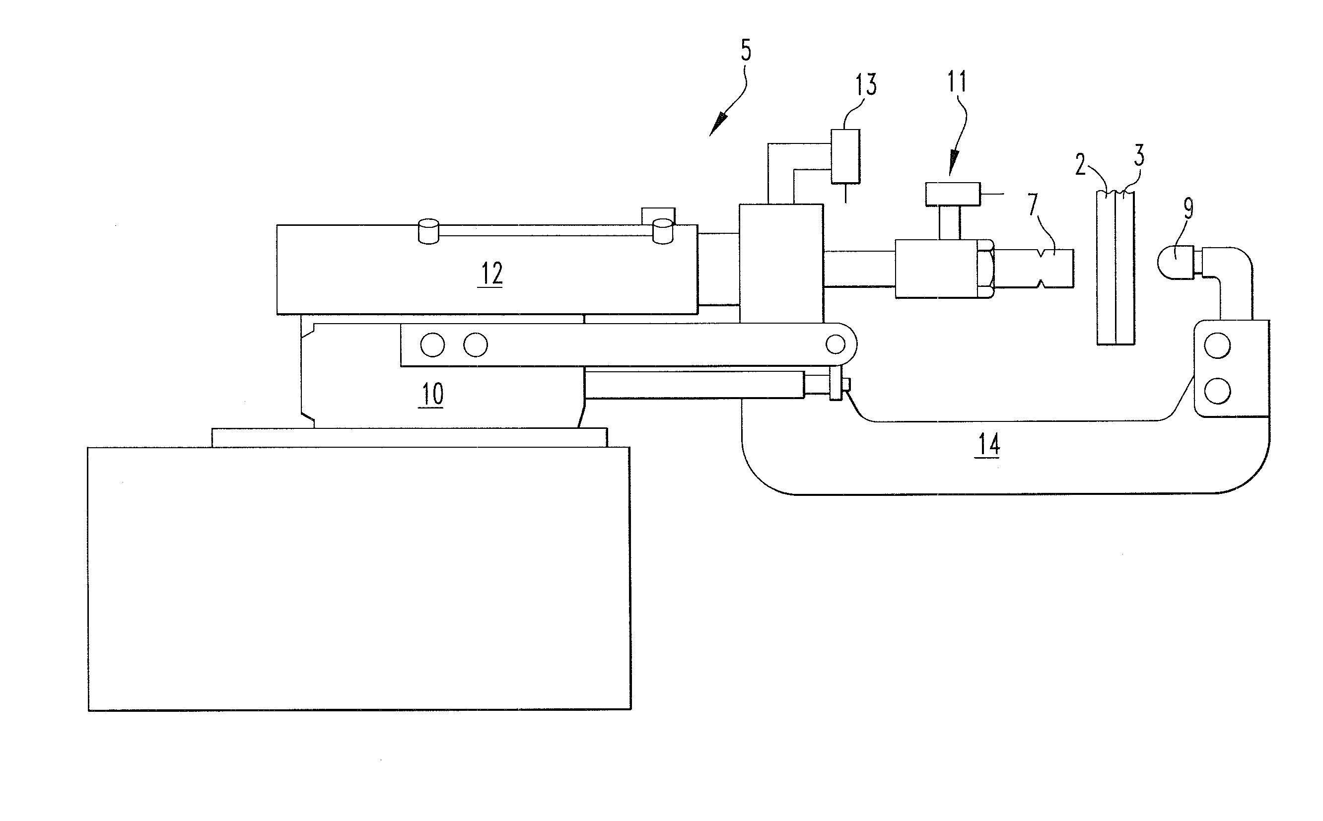
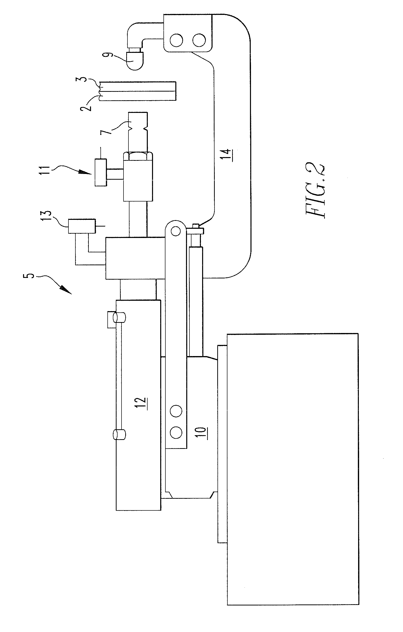
[0030]One example of a resistance welding apparatus is depicted in FIG. 2. The resistance welding apparatus 5 comprises a first electrode 7 positioned to contact a surface of a first metal sheet 2 during current and force applic...


PUM

PropertyMeasurementUnit
diameteraaaaaaaaaa
voltageaaaaaaaaaa
widthaaaaaaaaaa

Abstract

A method of resistance welding comprising the steps of contacting a metal sheet with an electrode having an initial contact surface area at a force to provide a pressure to the metal sheet applying a current through the electrode to the metal sheet; measuring dimensional changes of the electrode; correlating dimensional changes in the electrode to changes in the initial contact surface area; and adjusting the force to compensate for the changes in the initial contact surface area of the electrode to maintain pressure to the metal sheet. The force may be adjusted by stepping the force to maintain pressure to the faying surface of the metal sheet to be welded. By maintaining the pressure at the faying surface the life cycle of the electrodes may be increased without forming discrepant welds. The current may also be stepped to further extend electrode life.

Description

FIELD OF THE INVENTION[0001]The present invention relates to an electrical resistance welding method. More specifically, an electrical resistance welding process is provided that adjusts the force applied to the electrodes to correspond to dimensional changes in the electrode cross-section. By measuring the dimensional changes of the electrodes cross-section and adjusting the force applied to the electrodes to correspond to the dimensional changes in the electrode the welding process lifetime can be increased without degrading welding performance.BACKGROUND OF THE INVENTION[0002]Resistance spot welding of aluminum processes traditionally has a lower electrode life than gauged steel and coated steel resistance welding methods. Increased electrode life is desired because it reduces maintenance cost; increases weld quality, and most importantly yields higher production. One disadvantage of resistance welding of aluminum is erosion of the electrodes, which results in changes of the tip ...

Claims


Application Information

Patent Timeline
Patent Type & Authority Patents(United States)
IPC IPC(8): B23K11/24
CPCB23K11/252B23K11/253B23K11/0026B23K11/11B23K11/16B23K35/02B23K35/302B23K2101/18B23K2103/10B23K2103/15
Inventor SPINELLA, DONALD J.BROCKENBROUGH, JOHN R.FRIDY, JOSEPH M.
Owner ARCONIC INC
Why Eureka
Try Eureka