
Dual circuit wall switch occupancy sensor and method of operating same

a dual-circuit wall switch and occupancy sensor technology, applied in the field of occupancy sensors, can solve the problems of less than optimal sensitivity, mechanical constraints, and inefficient conventional manual switches

Active Publication Date: 2008-10-07
HUBBELL LIGHTING INC
View PDF23 Cites 34 Cited by
  • Summary
  • Abstract
  • Description
  • Claims
  • Application Information

AI Technical Summary

Benefits of technology

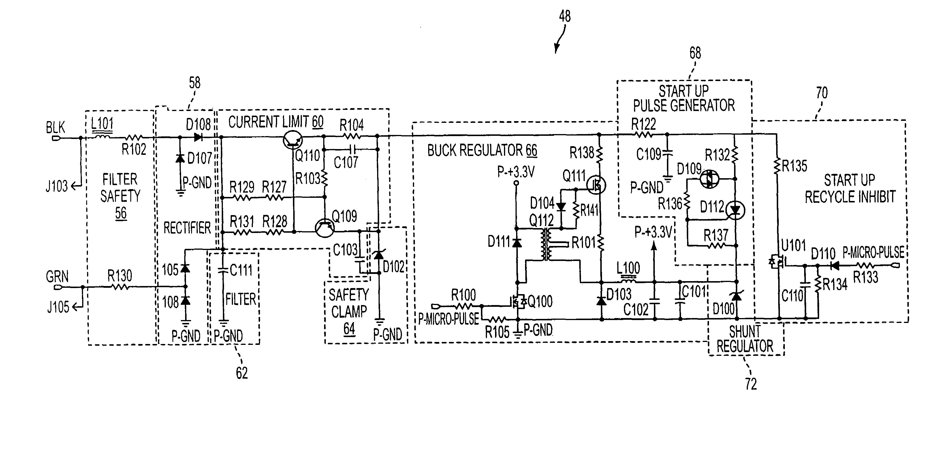
The present invention provides a method and apparatus for controlling power supply to an occupancy-based load controller. The invention solves the problem of existing occupancy sensors and power supplies by providing a more efficient and effective solution. The method involves selectively controlling the discharge of a capacitance circuit with a pulse signal, which allows for controlled power supply to a load connected between the power rail and ground. The pulse signal is generated by a current limiting circuit and an active occupancy detector. The power supply includes a rectifier circuit, a current limit circuit, and a regulator for controlling power supply to a DC load. The invention also includes an energy storage device, such as an inductor, for providing power to the DC power rail during the first portion of the pulse signal. The power supply can also include a shunt regulator and a start up pulse generator circuit for powering the microcontroller. The invention provides a more efficient and effective solution for controlling power supply to an occupancy-based load controller.

Problems solved by technology

Conventional manual switches are inefficient because they depend upon human judgment to turn all or only a portion of the lights on and off.
Existing automatic wall switches are more efficient, but still make errors, and have less than optimal sensitivity.
The wiring that exists in the existing switch enclosures, the mechanical constraints imposed by the existing switch enclosures, and the constraints presented by the existing loads cannot be easily altered and must be tolerated by the unit that is replacing the existing switch.
These types of power supplies are disadvantageous because they allow a small amount of current to flow in the load in off state, and that current may cause malfunction of certain electronic lamp ballasts.
These types of power supplies are also disadvantageous because they require a minimum amount of current flow to function with the load in the on-state, and because it is difficult for a single design to accommodate a large range of load current levels.

Method used


Image

  • Dual circuit wall switch occupancy sensor and method of operating same
  • Dual circuit wall switch occupancy sensor and method of operating same
  • Dual circuit wall switch occupancy sensor and method of operating same

Examples


Embodiment Construction

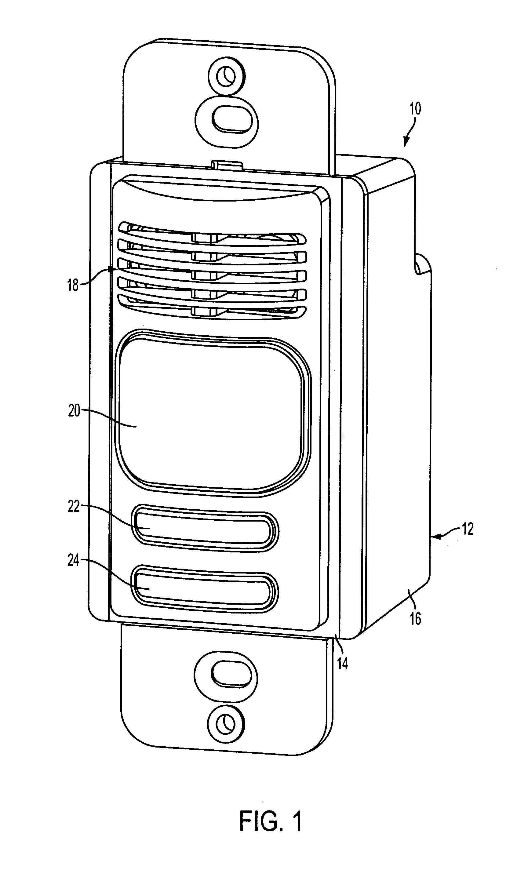
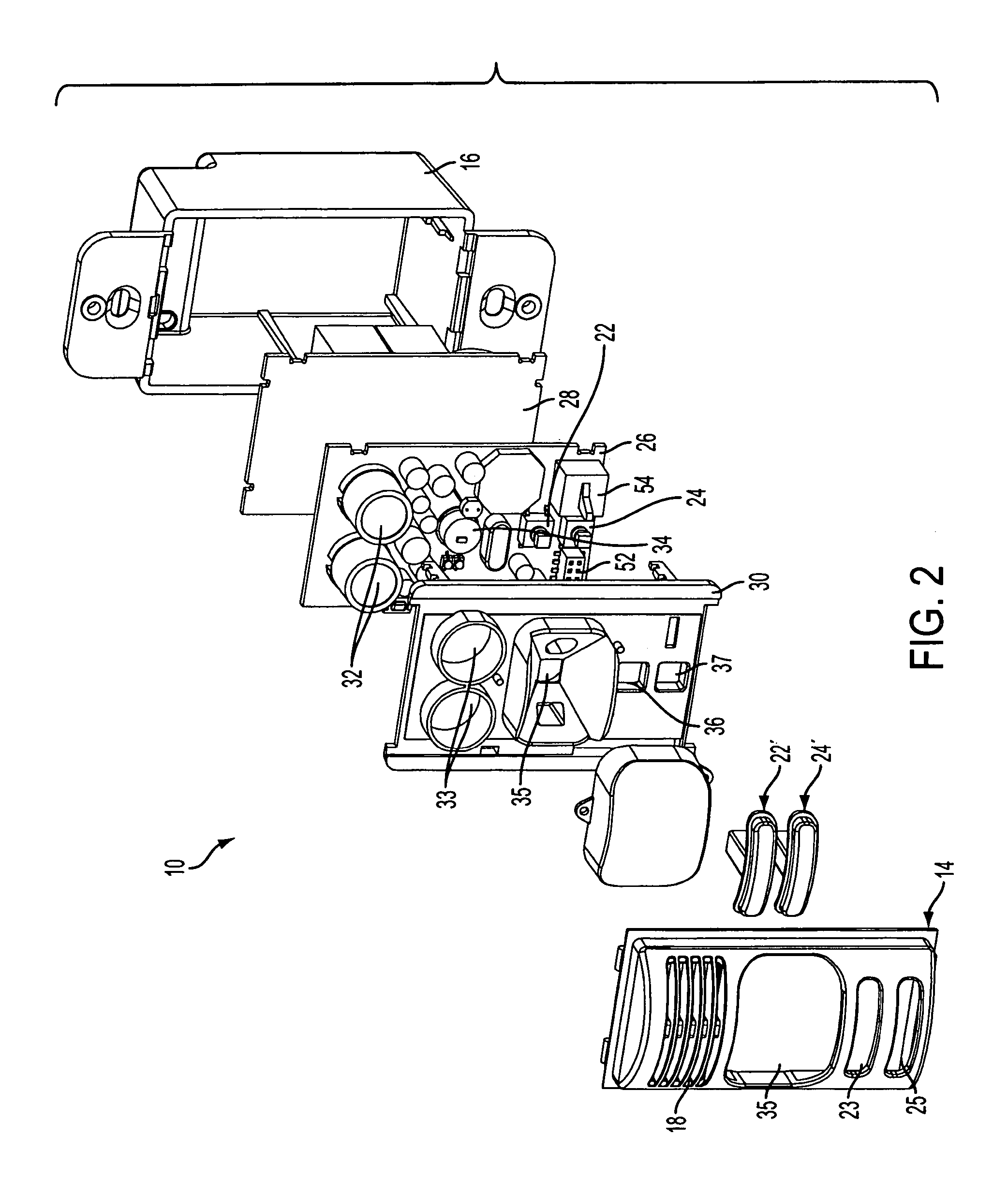
[0039]FIGS. 1 and 2 depict a dual circuit wall switch occupancy sensor device 10 in accordance with an embodiment of the present invention. The dual circuit wall switch occupancy sensor device is used to automatically control at least two lighting circuits (hereinafter referred to respectively as “circuit A” and “circuit B”) based on detection of human occupancy in a room. A lighting circuit can comprise one or more lamps. As stated above in the background, a device configured to control more than one lighting circuit in a room has the potential to reduce energy consumption by controlling, for example, one of plural lighting circuits that is deployed near a window or door to remain off when natural lighting or ambient light conditions near the window or door is sufficient for a user. It is to be understood, however, that the device can be configured to control more than two lighting circuits.

[0040]The device 10 preferably retrofits or mounts in an opening for a conventional electric...


PUM


Abstract

A method and apparatus are provided for detecting occupancy in an area using multiple detection technologies (e.g., ultrasound and infrared sensing) to intelligently control switching of plural load circuits whereby one of the circuits is affected by photocell control. A programmable controller implements auto-on, manual-on, reversion to auto-on and override operations with respect to the separately controlled load circuits based on sensor outputs and user inputs. An improved power supply for an occupancy sensor and load control device employs a DC voltage derived from leakage AC voltage between line and ground to drive the sensors and other circuits, and a switching regulator with a switching cycle controlled by a pulse width modulated (PWM) subsystem of the apparatus, allowing synchronous, delayed or exclusive operation relative to the sensing technology such as the US transmitter.

Description

CROSS-REFERENCE TO RELATED APPLICATIONS[0001]Related subject matter is disclosed in co-pending U.S. patent application Ser. No. 29 / 230,825 of R. Kurt Bender et al., filed even date herewith, entitled “Occupancy Sensor Fascia Cover Plate”; and in co-pending U.S. patent application Ser. No. 11 / 138,911 of R. Kurt Bender et al., filed even date herewith, entitled “Occupancy Sensor Assembly”; the entire contents of each of these applications being expressly incorporated herein by reference.FIELD OF THE INVENTION[0002]The present invention relates generally to occupancy sensors, and more particularly to an occupancy sensor and load control device for detecting occupancy in an area using multiple detection technologies such as ultrasound (US) and passive infrared (PIR) sensing to intelligently control switching of plural loads. Further, the present invention relates to an improved power supply for use with an occupancy sensor and load control device that employs a DC voltage derived from l...

Claims


Application Information

Patent Timeline
Patent Type & Authority Patents(United States)
IPC IPC(8): G05F1/563G05F1/613
CPCH05B37/0218H05B37/0227Y02B20/46Y10S323/908H05B47/11Y02B20/40H05B47/13G05F1/46H02M3/156H03K3/57
Inventor WILLIAMS, JONATHAN D.BLACKMAN, TODDHARTNAGEL, THOMAS J.KONRADI, VADIM
Owner HUBBELL LIGHTING INC
Learn More