Bi-directional isolated DC/DC converter

a converter and bi-directional technology, applied in the direction of electric variable regulation, process and machine control, instruments, etc., can solve the problems of galvanic separation, classical isolated converters that use transformers and do not offer bi-directionality, etc., and achieve the effect of wide high voltage and low voltage side regulation rang

Inactive Publication Date: 2008-10-07
ASBU HLDG
View PDF16 Cites 23 Cited by
  • Summary
  • Abstract
  • Description
  • Claims
  • Application Information

AI Technical Summary

Problems solved by technology

Classical bi-directional converters are made with multi-stage interleaved buck / boost converters which do not offer galvanic separation between the high voltage and low voltage side and which require substantial heatsink space for the voltage range described and the power range applicable, for example approximately 1500 watts.
Also, classical isolated converters that use transformers do not offer bi-directionality.

Method used


Image

  • Bi-directional isolated DC/DC converter
  • Bi-directional isolated DC/DC converter
  • Bi-directional isolated DC/DC converter

Examples


Embodiment Construction

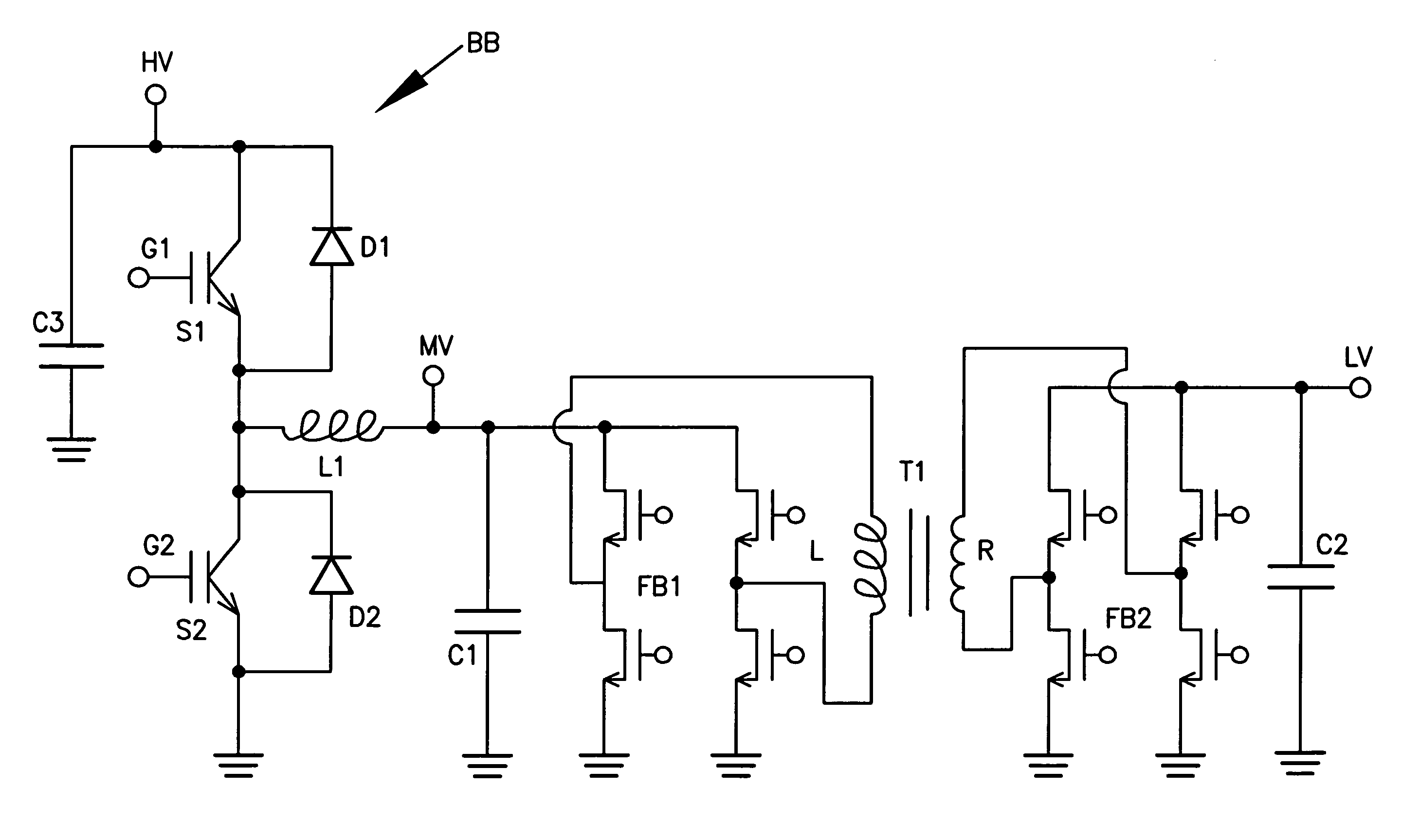
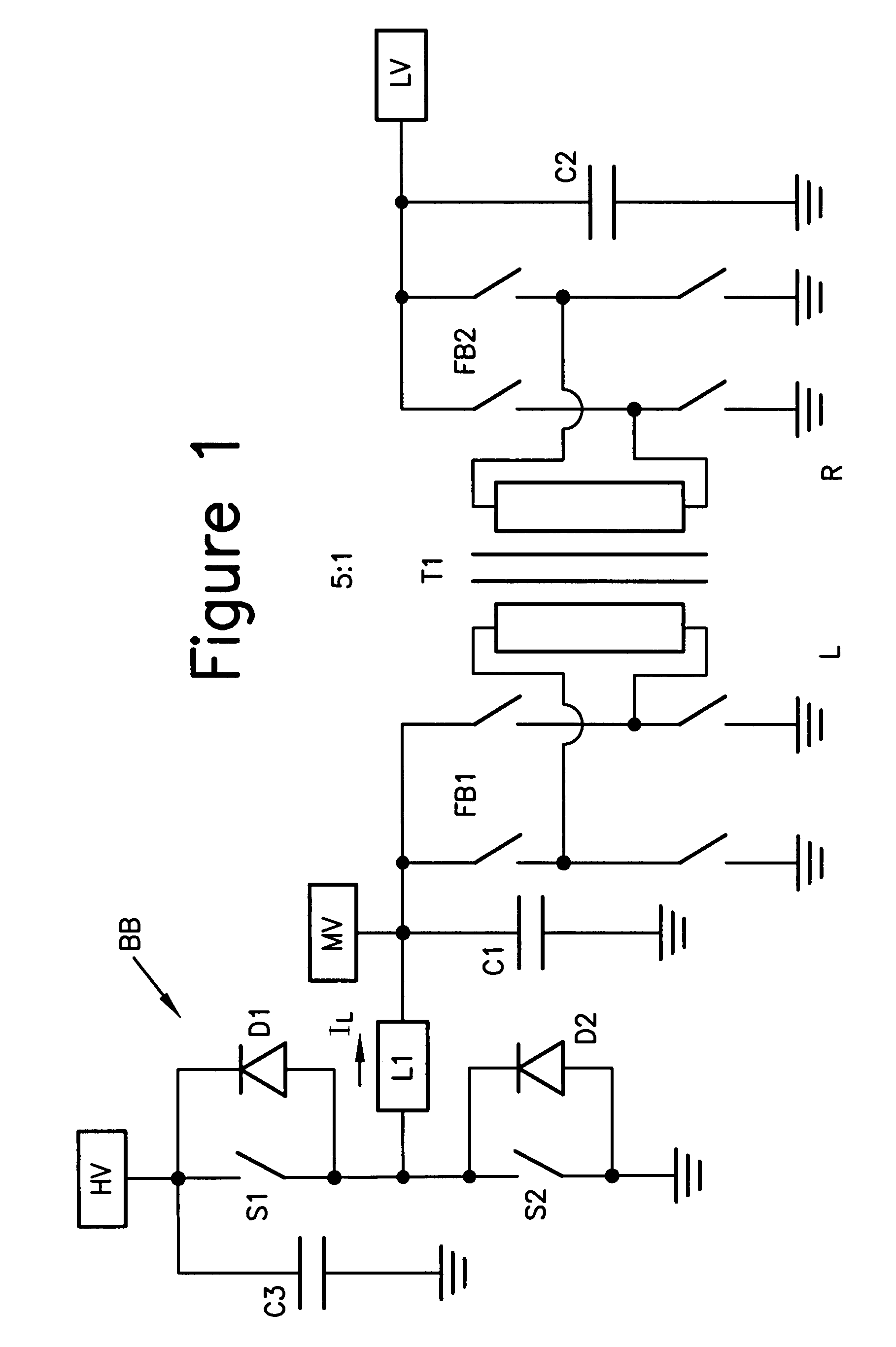
[0013]With reference now to FIG. 1, the bi-directional converter of the invention comprises a transformer T1 having, for example, a turns ratio of, for example, 5:1 from the winding designated L to the winding designated R thereby providing a voltage step down function going from left to right and a step up function going from right to left. On the winding L side, a full bridge FB1 is connected across the winding. On the winding R side, a full bridge FB2 is connected across the winding. The switches of the bridges may be MOSFETs. The low voltage (LV) side has a capacitor C2 connected thereacross. A capacitor C1 is connected across the full bridge FB1 and establishes a bus MV or medium voltage bus.

[0014]A bi-directional buck / boost converter BB is provided between the high voltage bus HV and the bus MV. The bi-directional buck / boost converter BB may be realized with two fast 600 volt IGBTs S1 and S2 and their anti-parallel connected diodes D1 and D2, plus the storage inductor L1. The ...


PUM


Abstract

A bi-directional converter for converting voltage bi-directionally between a high voltage bus and a low voltage bus, having a switching converter connected across the high voltage bus, the switching converter having first and second switching modules connected in series across the high voltage bus, a switched node disposed between the switching modules being coupled to an inductor, the first and second switching modules being controllable so that the switching converter can be operated as a buck converter or a boost converter depending upon the direction of conversion from the high voltage bus to the low voltage bus or vice versa; the mid-voltage bus being coupled to a first full bridge switching circuit having two pairs of series connected switches with switched nodes between each of the pairs of switches being connected across a first winding of a transformer having a preset turns ratio.

Description

CROSS REFERENCE TO RELATED APPLICATIONS[0001]This application claims the benefit and priority of U.S. Provisional Application Ser. No. 60 / 782,651 filed Mar. 15, 2006 and entitled 1500 W BI-DIRECTIONAL ISOLATED DC / DC CONVERTER, the entire disclosure of which is incorporated by reference herein.BACKGROUND OF THE INVENTION[0002]The present invention relates to switching converters, and in particular to bi-directional switching converters. The present invention can be used in automotive as well as industrial applications where a wide DC high voltage range from 100 volts to 450 volts, for example, needs to be converted to a wide DC low voltage range from 7 volts to 16 volts, for example, and vice versa, with galvanic isolation between the two sides.[0003]Classical bi-directional converters are made with multi-stage interleaved buck / boost converters which do not offer galvanic separation between the high voltage and low voltage side and which require substantial heatsink space for the vol...

Claims


Application Information

Patent Timeline
Patent Type & Authority Patents(United States)
IPC IPC(8): H02M3/335H02M7/5387H02M7/00
CPCH02M3/33569H02M3/33592H02M7/797H02M2001/007Y02B70/1475Y02B70/10H02M1/007H02M3/33573
Inventor THOR, VOLKERBLEUKX, MARC
Owner ASBU HLDG
Why Eureka
Try Eureka