System and a method for prediction and treatment of slugs being formed in a flow line or wellbore tubing

a flow line or wellbore tubing and slug technology, applied in the directions of water supply installation, transportation and packaging, borehole/well accessories, etc., to achieve the effect of eliminating the disadvantages of the former system

Active Publication Date: 2008-10-14
DEN NORSKE STATS OLJESELSKAP AS
View PDF10 Cites 26 Cited by
  • Summary
  • Abstract
  • Description
  • Claims
  • Application Information

AI Technical Summary

Benefits of technology

[0034]In light of the shortcomings mentioned above, the inventors have found that there is a need for a more efficient method and system for prediction and treatment of slugs. The present invention describes a method and a system applicable in connection with a downstream process in which the disadvantages of former systems have been eliminated. The basic idea is to

Problems solved by technology

Further, if these slugs are “large” compared to the design of the downstream equipment, the fluctuations could propagate into the process and reach a level untenable to the operators.
Slugging is by definition a transient phenomenon, and steady state conditions are hard to achieve in a slugging flow line system.
These “traditional” methods will either reduce production from the flow line systems in question or increase the costs and dimensions of the downstream process.
Additionally, even if accounted for, slugs might grow larger than expected or could occur at unfortunate moments compared to actual process capabilities.
As a consequence, the pressure and flow fluctuations could result in process shut-downs, which might have significant financial impacts.
If the estimated volume of the incoming slugs exceeds the liquid slug handling capacity of the separator, a throttling valve located upstream of the separator is choked.
However, the system entails some major disadvantages:Since the flow rate is being throttled down, it has a negative impact on the production and thereby the field economics.It does not take into account the slug handling capacity in the downstream process.It does not describe how gas slugs are identified and treated.
As a consequence pressure fluctuations in the separator due to incoming gas slugs must still be solved by gas flaring.The system does not separate water slugs from hydrocarbon (HC) liquid slugs which could give process perturbations downstream of a three-phase separator.It prolongs the start-u

Method used


Image

  • System and a method for prediction and treatment of slugs being formed in a flow line or wellbore tubing
  • System and a method for prediction and treatment of slugs being formed in a flow line or wellbore tubing
  • System and a method for prediction and treatment of slugs being formed in a flow line or wellbore tubing

Examples


Embodiment Construction

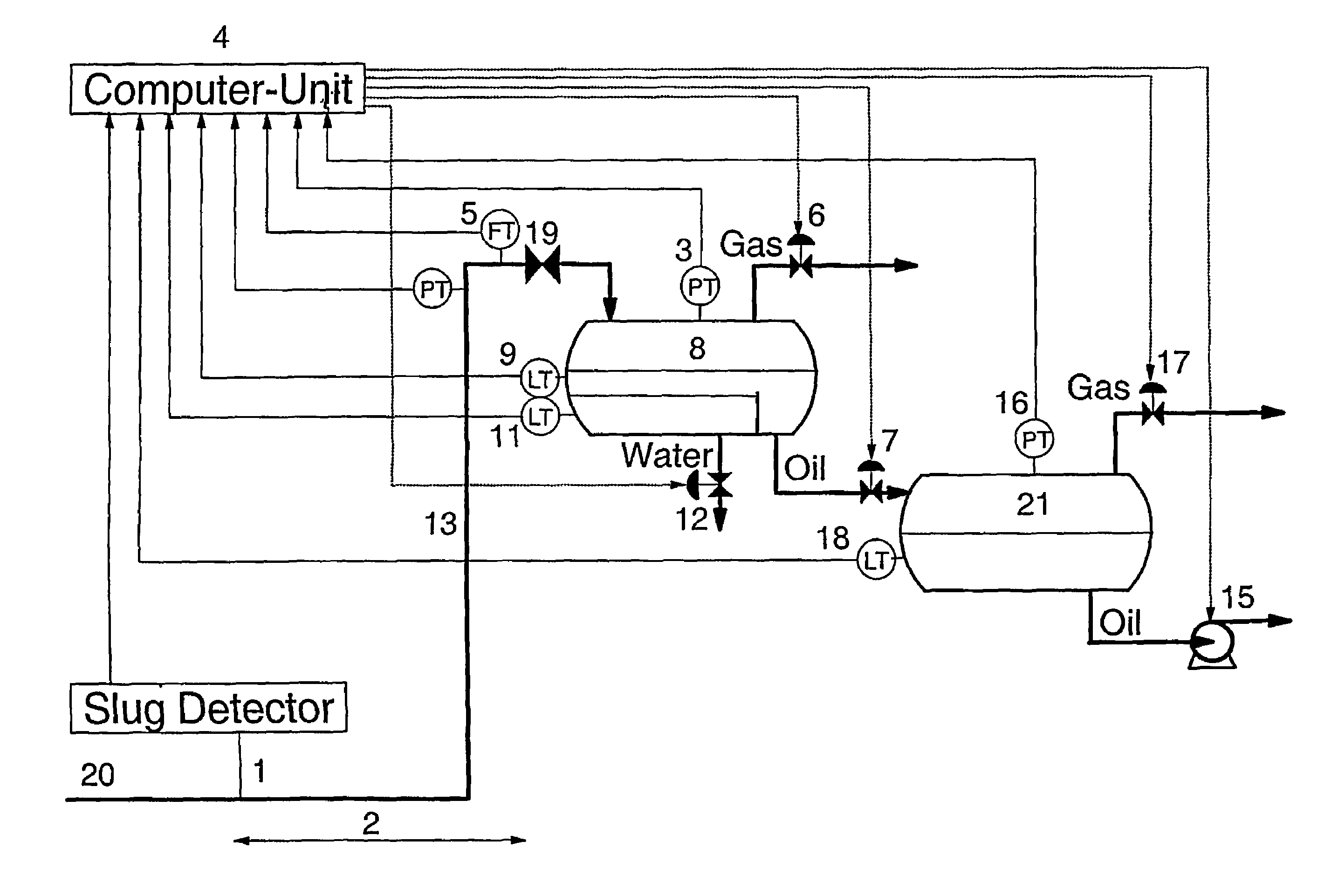
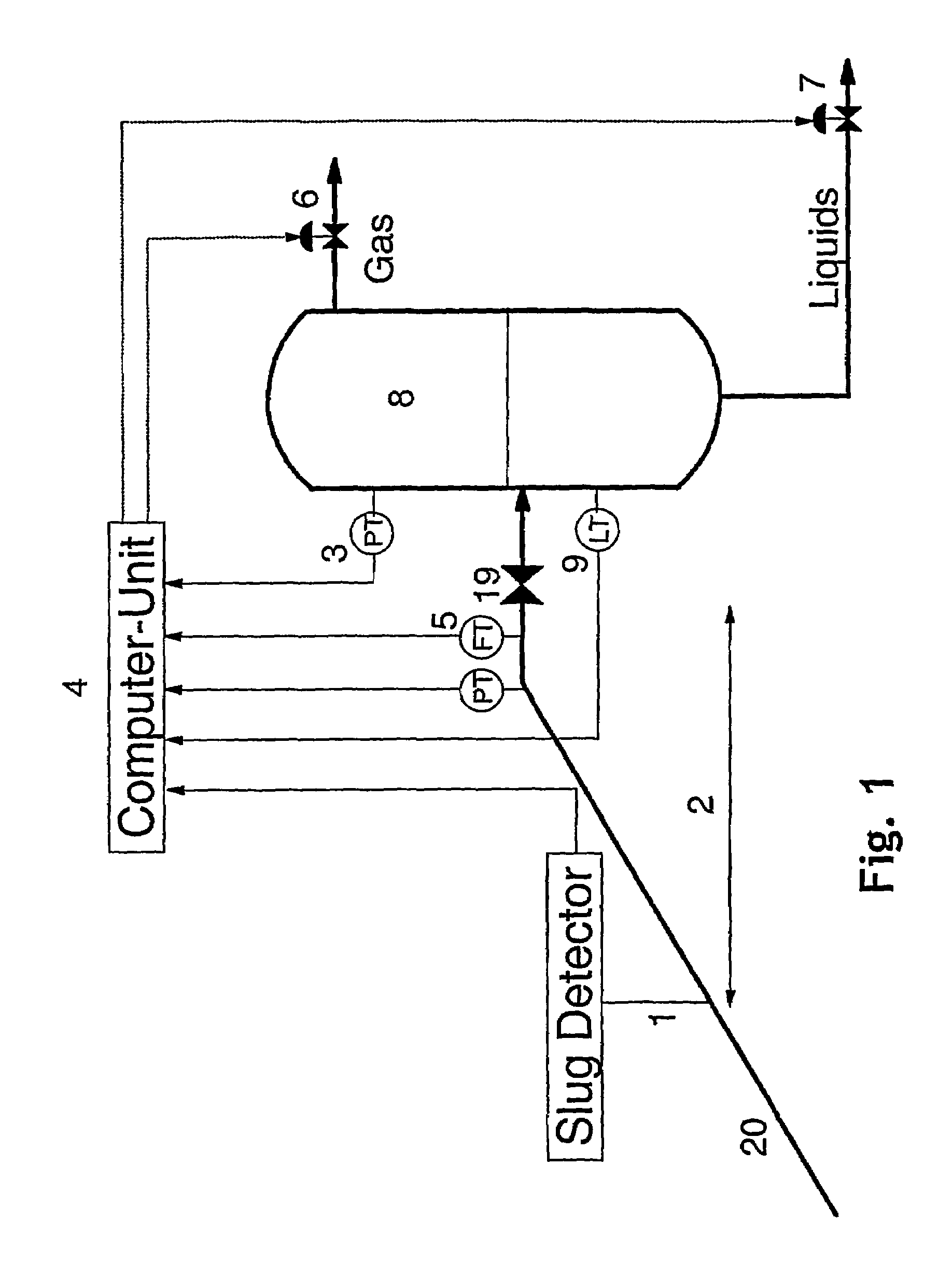
[0041]FIG. 1 shows a process diagram of the present invention in its simplest form implemented in an offshore production system producing towards an onshore process including a vertical two-phase slug catcher 8 at the inlet of the process. It is further seen that the slug catcher pressure 3 is controlled by adjustment of a gas outlet valve 6. Correspondingly, its liquid level 9 is controlled by adjustment of a liquid outlet valve 7.

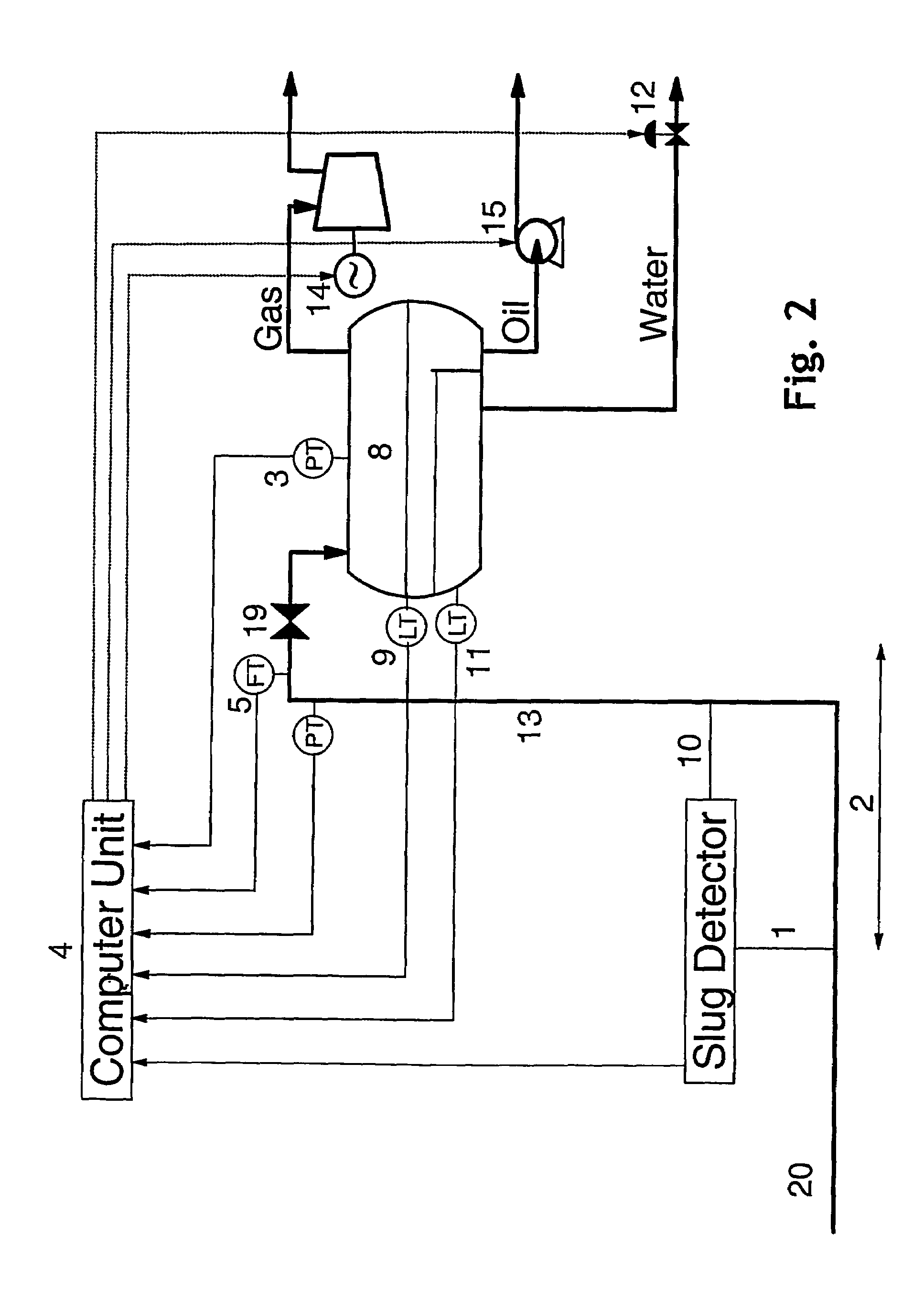
[0042]A simple description of the invention is as follows: The distance 2 between the slug detector 1 and the process has been optimized with respect to the process and its parameters for regulation. When the slug detector 1 detects a liquid slug, the computer unit 4 determines its nature and calculates its arrival time and volume. Based on this information and the current liquid level 9 in slug catcher 8, the computer unit immediately sends a signal to the liquid valve 7 to start liquid draining of the slug catcher 8, prior to slug arrival. When the liqu...


PUM


Abstract

A system and a method for prediction and treatment of all kinds of slugs being formed in a flow line system or wellbore tubing transporting a multiphase fluid towards a downstream process including a separator or a slug catcher at the process inlet. The system includes a slug detector (1) located downstream of the point for slug initiation and upstream of the process and a computer unit (4) integrating the flow line system and the downstream process including software which determines the type of the slug, its volume and predicts its arrival time into the downstream process. The computer unit processes all its incoming data to obtain an optimum regulation of the process so that process perturbations due to incoming slugs are reduced to a minimum through the process.

Description

BACKGROUND OF THE INVENTION[0001]1. Technical Field[0002]The present invention relates to a method and a system for prediction and treatment of hydrodynamic and terrain-induced slugs being transported in a multi-phase flow line.[0003]The method and the system according to the present invention can be adapted to any production system, e.g. flow line system or wellbore tubing, transporting a multiphase fluid towards a downstream process including a separator (two- or three-phase) or a slug catcher at the inlet, in which there is regulation of both pressure and liquid level(s). The multiphase fluid normally consists of a mixture of an oil (or a condensate) phase, gas and water.[0004]2. Description of Related Art[0005]A typical production system where the present invention could be implemented includes multiphase transport from platform wells, from subsea wells towards a subsea separator, from a subsea production template towards an offshore platform including a riser, between offshore ...

Claims


Application Information

Patent Timeline
IPC IPC(8): E21B43/12E21B41/00E21B43/34
CPCE21B43/00E21B43/34Y10T137/0318Y10T137/3052
Inventor AARVIK, ASBJORNUV, EGIL HENRIK
Owner DEN NORSKE STATS OLJESELSKAP AS
Why Eureka
Try Eureka