Power system for electric and hybrid vehicles

a technology for electric and hybrid vehicles, applied in the direction of wind turbines with solar radiation, machines/engines, propulsion parts, etc., can solve the problems of high cost of petroleum products, low mileage gain achieved by such hybrid vehicles, and insufficient reduction of petroleum consumption of supplementing combustion engine power with electric engine power

Inactive Publication Date: 2008-10-14
SUTHERLAND DANILO R
View PDF35 Cites 116 Cited by
  • Summary
  • Abstract
  • Description
  • Claims
  • Application Information

AI Technical Summary

Problems solved by technology

However, with the rising cost of petroleum products, namely gasoline and diesel, an alternative method for powering automobiles is needed.
However, the mileage gains achieved by such hybrid vehicles still tend to be modest, at best.
With only modest gains in mileage by hybrid automobiles, supplementing combustion engine power with electric engine power does not offer a sufficient reduction in petroleum usage.
However, one of the primary drawbacks of electric vehicles is their very limited range.
However, Moore dies not include any method for charging the electrical system at night, or during overcast conditions when an external charger is not available.
However, Tolinski does not disclose using the solar cells to provide electrical power sufficient to drive the vehicle electrically, nor does Tolinski disclose a method for charging the electrical system by any method other than a solar cell.
The drawback to charging an electric vehicle solely with a non-portable charging device is that when driving an electric vehicle, with its inherently short range, drivers face a risk of being stuck in an area where a charger is not available.

Method used


Image

  • Power system for electric and hybrid vehicles
  • Power system for electric and hybrid vehicles
  • Power system for electric and hybrid vehicles

Examples


Embodiment Construction

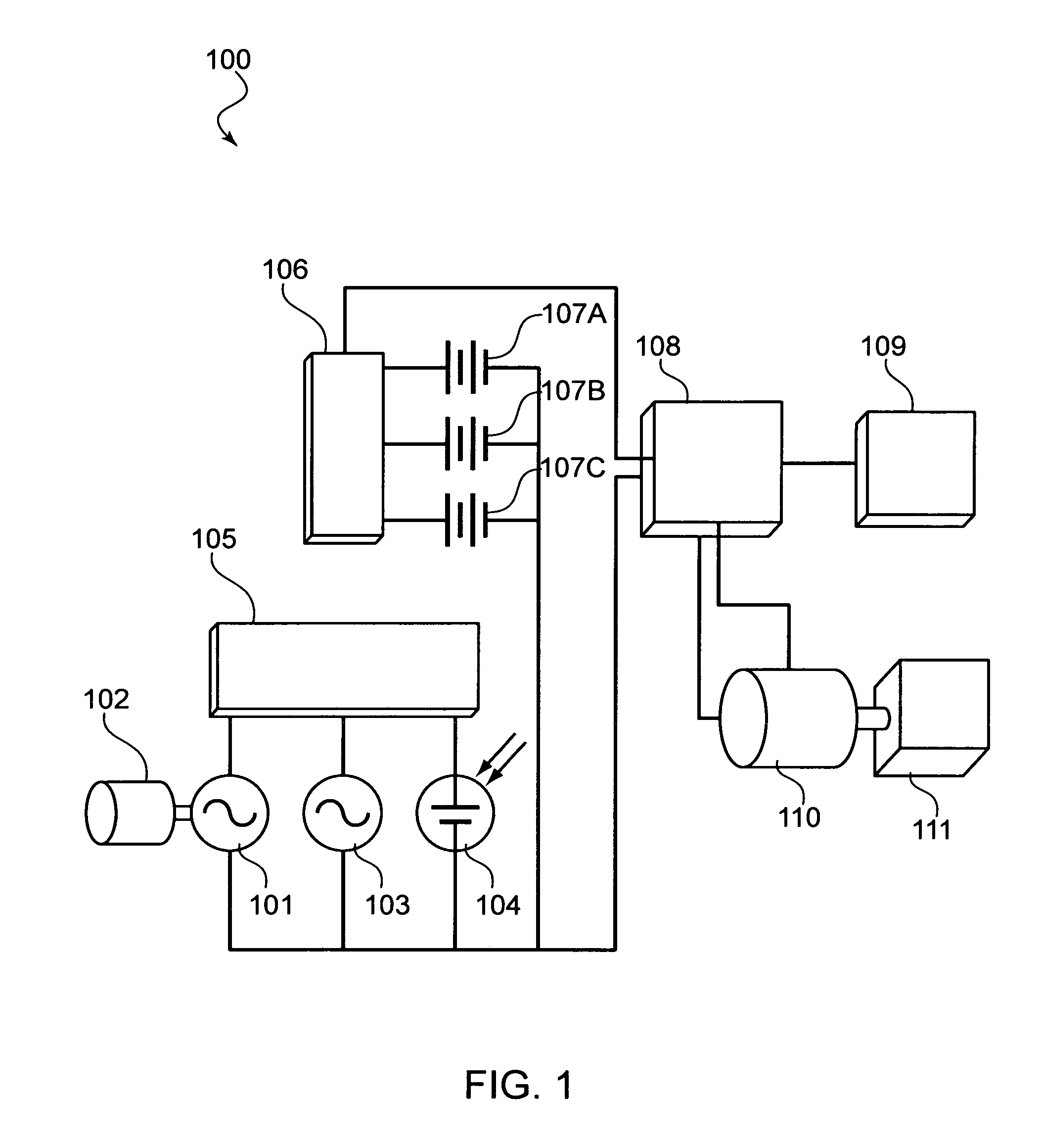
[0023]Referring now to the Figures, where like numbers indicate like features, the illustration of FIG. 1 depicts a block diagram illustrating an exemplary layout and interconnectivity of devices comprising a power system for electric and hybrid vehicles 100 (hereinafter, power system).

[0024]The power system 100 may include a power generating device 101 such as, but not limited to, an alternator or electrical generator connectively attached to an auxiliary internal combustion motor 102. In one exemplary embodiment, the auxiliary motor may be a small internal combustion motor left in an idle or stopped state until needed to drive the power generating device. In a particularly useful embodiment, the auxiliary motor 102 may be started and used to drive the power generating device 101 to generate power sufficient to charge any batteries (107A-C) disposed within the power system 100, allowing a driver to continue use of a vehicle within which the power system 100 is disposed.

[0025]The po...


PUM


Abstract

A power system for an electric vehicle, the power system comprising at least one power generating device selected from a group consisting of a solar panel, a wind turbine capable of producing electrical power, an auxiliary generator driven by an internal combustion engine, and a generator for producing electrical power mechanically connected to, and driven by the rotational force of an axle of a vehicle. The power system being further comprised of a charging device, a battery control device, at least one battery, a motor control device, an electric drive motor electrically connected to the motor control device, and a driver interface connected to the motor control device. The electric drive motor may be used to generate power through regenerative braking. The wind turbine may be raised outside the body of a vehicle while the vehicle is not in motion. The solar panel may be disposed outside the vehicle while remaining electrically connected to the charging device.

Description

PRIORITY[0001]This application claims the benefit of the filing date of Provisional Application No. 60 / 663,078, filed Mar. 18, 2005, and which is herein incorporated by reference.BACKGROUND OF THE INVENTION[0002]1. Technical Field[0003]The present invention relates generally to electrical vehicle power systems, and more specifically to an electric vehicle power system with at least one integrated charging system.[0004]2. Background of the Invention[0005]The internal combustion engine has been commonly used for many decades as the motive power for automobiles. However, with the rising cost of petroleum products, namely gasoline and diesel, an alternative method for powering automobiles is needed.[0006]Recently, several manufacturers have introduced hybrid vehicles to the market in an effort to provide consumers with an opportunity to obtain more fuel efficient automobiles. Currently, systems such as Toyota's® Hybrid Synergy Drive® pair an electric engine with a conventional petroleum...

Claims


Application Information

Patent Timeline
Patent Type & Authority Patents(United States)
IPC IPC(8): B60K16/00
CPCB60K6/46B60K16/00B60L11/126B60W10/26F03D9/002B60L8/006B60K2016/003B60K2016/006B60W20/00B60W2510/244F05B2240/941Y02T10/6217Y02T10/6269Y02T10/7005Y02T10/7077Y02T10/7083Y02T10/90Y02E10/725Y10S903/903F03D9/25Y02E10/728B60L50/62F03D13/20F03D9/32F03D9/007H02S10/12Y02E10/50Y02E10/72Y02T10/62Y02T10/7072Y02T10/70F03D13/10
Inventor SUTHERLAND, DANILO R.
Owner SUTHERLAND DANILO R
Why Eureka
Try Eureka