Buck converter having improved transient response to load step down

a buck converter and load step technology, applied in the direction of electric variable regulation, process and machine control, instruments, etc., can solve the problems of large and costly output capacitors used to reduce the overshoo

Active Publication Date: 2008-10-14
INFINEON TECH AMERICAS CORP
View PDF2 Cites 11 Cited by
  • Summary
  • Abstract
  • Description
  • Claims
  • Application Information

AI Technical Summary

Problems solved by technology

Since the overshoot is inversely proportional to the output capacitance, traditionally large and costly output capacitors are used to reduce the overshoot.

Method used


Image

  • Buck converter having improved transient response to load step down
  • Buck converter having improved transient response to load step down
  • Buck converter having improved transient response to load step down

Examples


Embodiment Construction

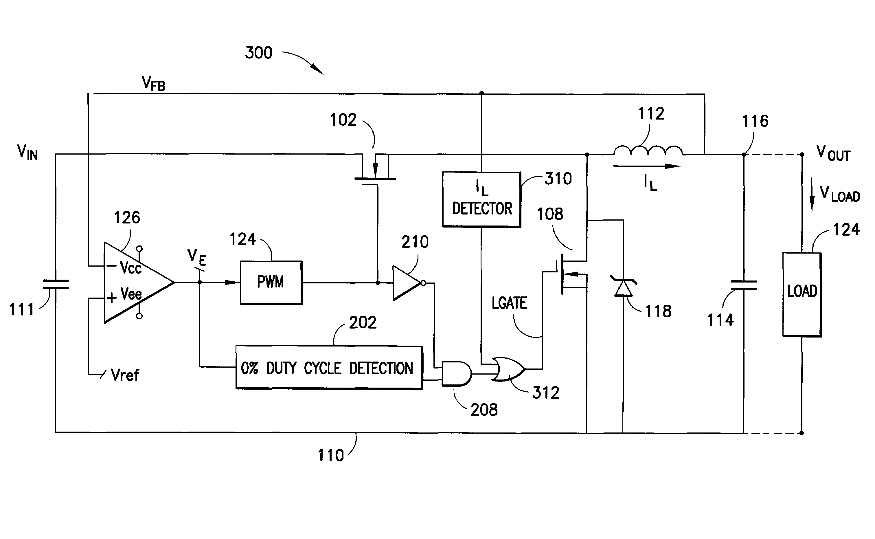
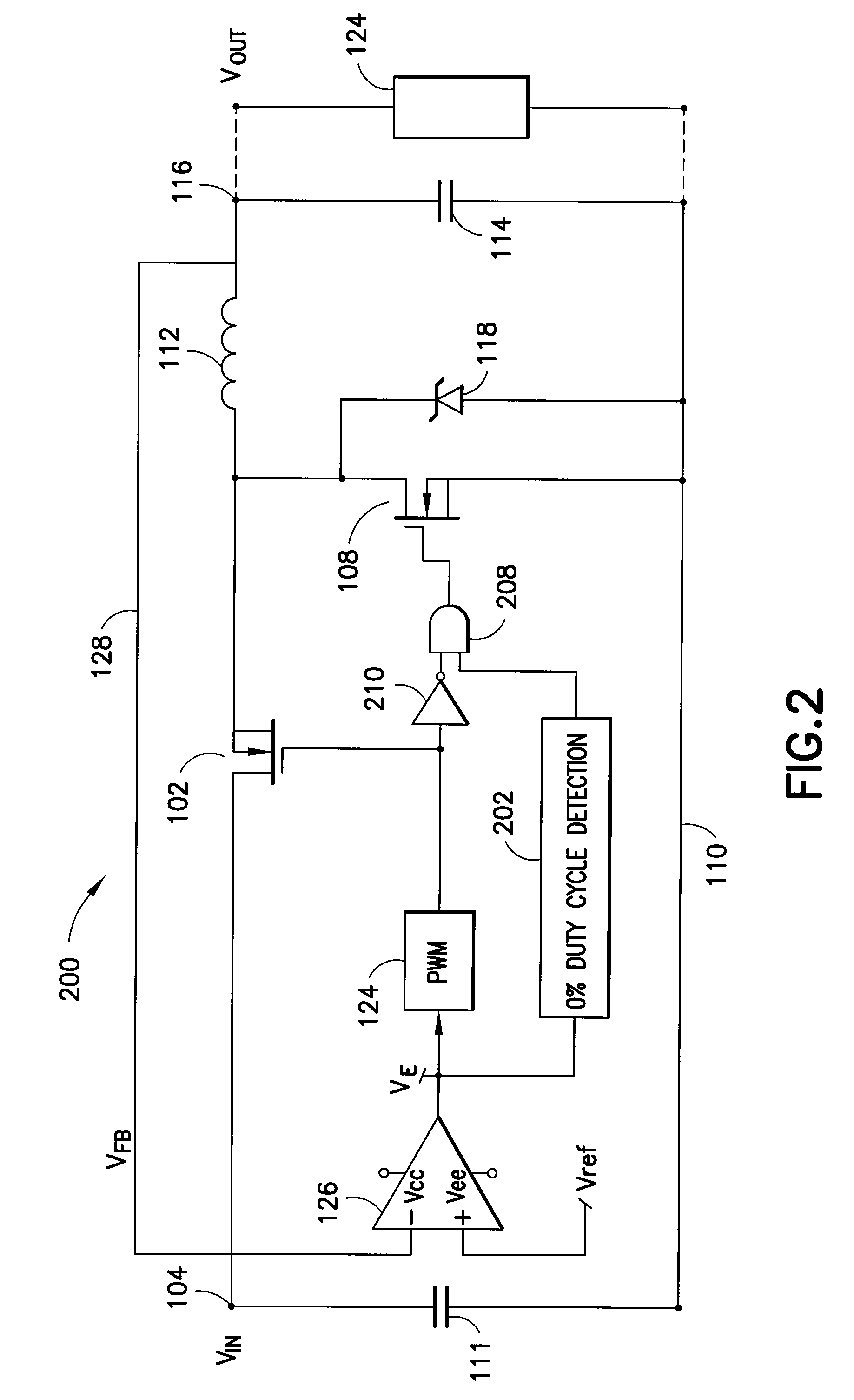
[0026]FIG. 3 illustrates a buck converter circuit 300 in accordance with an embodiment of the present application. The circuit of FIG. 3 is similar to that of FIG. 2 and common elements are referred to by the same reference numerals. The circuit of FIG. 3 differs from that of FIG. 2 in that an inductor current sensing device 310 is provided to sense when the inductor dissipating current IL reaches zero. An output of the inductor current sensing device is then used to turn the lower MOSFET 108 ON when the inductor current is zero.

[0027]In operation, in the converter circuit 300 of FIG. 3, in the event of a step down in load current ILOAD, the zero duty cycle sensor 202 detects whether the duty cycle of the series transistor 102 is 0%. If so, a control signal from the zero duty cycle sensor is provided to shut off the lower MOSFET 108 in order to gain the benefits of body breaking as described above with reference to the '723 patent. The inductor current sensing device 310, meanwhile ...


PUM


Abstract

A synchronous buck converter having an improved transient response during output current includes a first switching transistor connected between an input node and a first node, a second switching transistor connected between the first node and a second node, a series inductor connected between the first node and an output node, an output capacitor connected between the output node and the second node, a first driver circuit operative to turn the first switching transistor one and off according to a variable duty cycle determined by an error signal representing the difference between the voltage output of the converter and a reference voltage, a sensing circuit operative to provide a control signal output when the duty cycle for the first switching transistor is zero, a second drive circuit responsive to the control signal output of the sensing circuit to turn off the second switching transistor and a second sensing circuit operative to provide a second control signal when a dissipating current of the inductor is zero, wherein the second drive circuit is responsive to the second control signal to turn the second switching transistor on when the dissipating current of the inductor is zero.

Description

REFERENCE TO RELATED APPLICATIONS[0001]The present application claims benefit to and priority from U.S. Provisional Patent Application No. 60 / 671,561 entitled BUCK CONVERTER HAVING INPROVED TRANSIENT RESPONSE TO LOAD STEP DOWN filed Apr. 15, 2005, the entire contents of which are hereby incorporated by reference herein.BACKGROUNDRelated Art[0002]FIG. 1 illustrates a basic configuration of a synchronous buck converter. The circuit 100 includes a series switch 102 which is typically a power MOSFET or the like, with its source-drain path connected between an input terminal 104 and a first signal node 106, a shunt switch 108, also typically a power MOSFET or the like, and an output circuit comprised of a series inductor 112 and a shunt capacitor 114 connected to inductor 112 at a signal output node 116 and to ground 110. A shunt diode such a Shottky diode 118 may also be provided in parallel with MOSFET 108 if desired to provide conduction during the deadtimes of the switch 108 to reduc...

Claims


Application Information

Patent Timeline
Patent Type & Authority Patents(United States)
IPC IPC(8): G05F1/00
CPCH02M3/1588H02M2001/0009Y02B70/1466H02M1/0009Y02B70/10
Inventor WALTERS, MIKE
Owner INFINEON TECH AMERICAS CORP
Why Eureka
Try Eureka