Stacked microstrip patches

Active Publication Date: 2008-10-14
AERO ANTENNA
View PDF9 Cites 57 Cited by
  • Summary
  • Abstract
  • Description
  • Claims
  • Application Information

AI Technical Summary

Benefits of technology

[0013]It is an object of the invention to provide reduced back radiation compared to other dual frequency circularly polarized stack patches.
[0014]It is an object of the invention to provide an antenna with increased overall gain compared with other dual frequency circularly polarized stack patches.
[0015]It is an object of the invention to provide an antenna with excellent circularity at all radiation angles for the hemisphere above the ground plane.
[0016]It is an object of the invention to provide an antenna with performance at least the equa

Problems solved by technology

Surface waves interfere with desired antenna gain, bandwidth, and cross-polarization levels for microstrip antennas.
G

Method used


Image

  • Stacked microstrip patches
  • Stacked microstrip patches
  • Stacked microstrip patches

Examples


Embodiment Construction

[0025]The invention is now discussed with reference to the figures.

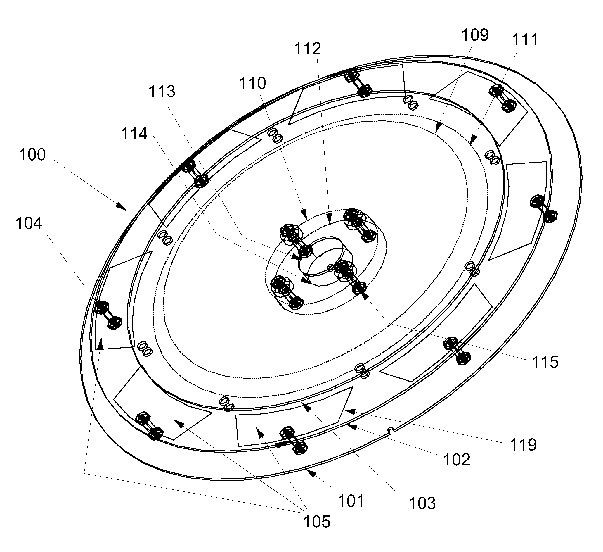
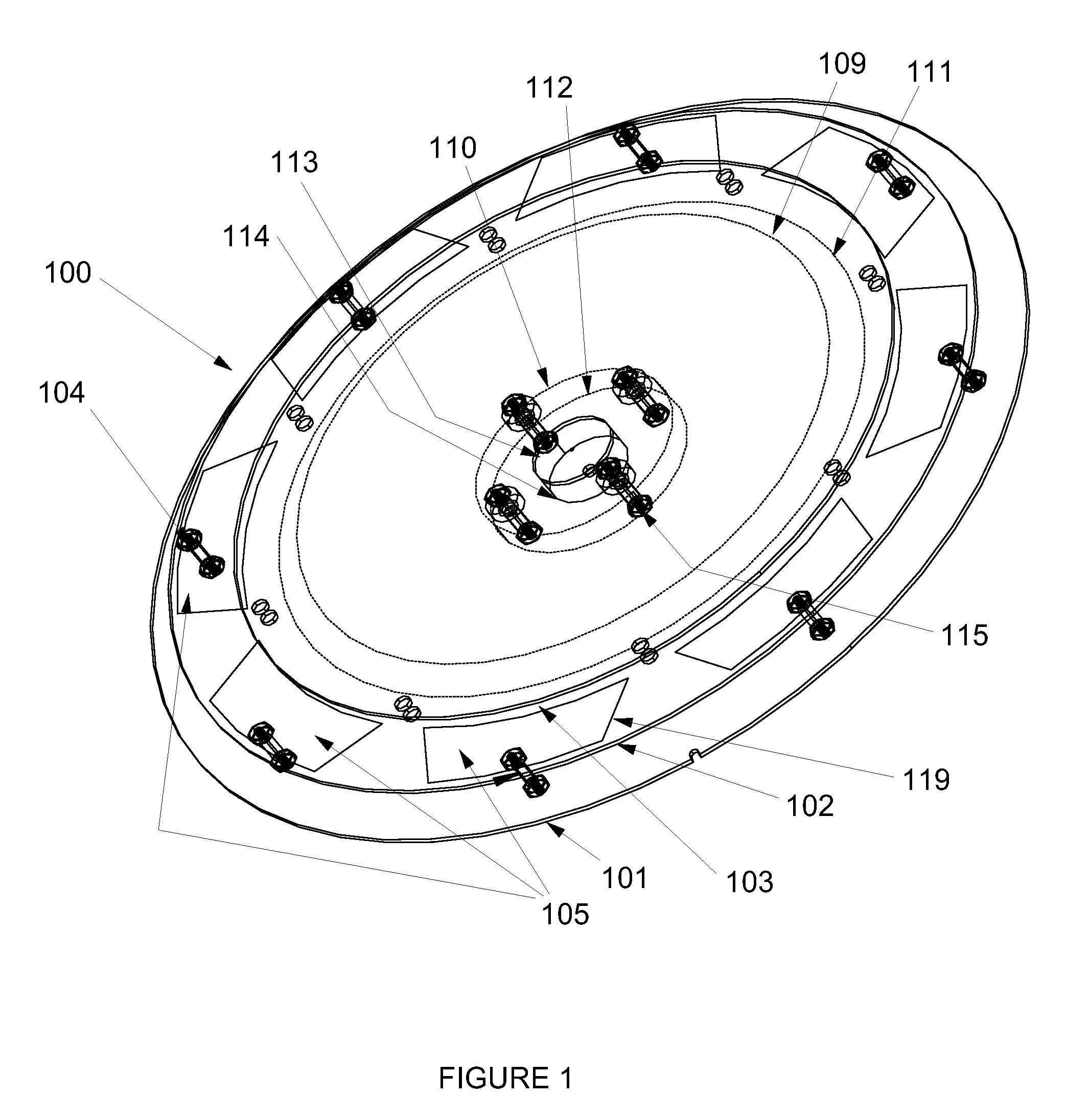
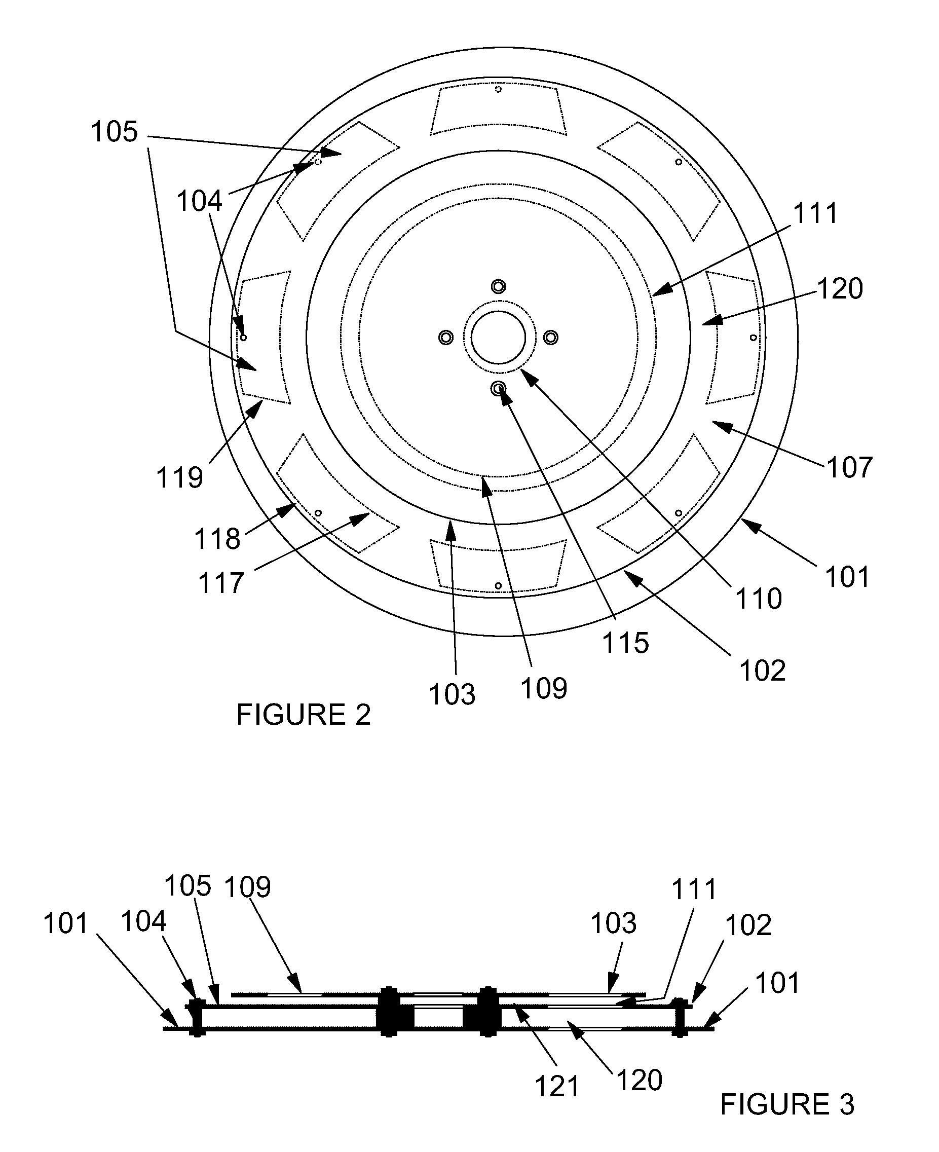
[0026]Antenna 100 is shown in FIGS. 1 through 3 having three support layers 101, 102 and 103 for respectively a ground layer, a mid layer, and a top layer. Layers 101, 102 and 103 are formed of an appropriate dielectric material. Layer 101 is connected with appropriate circuitry so that is acts as a ground layer for microstrip patches formed on layers 102 and 103, respectively a mid microstrip patch with outer boundary 111 and a top microstrip patch with inner boundary 110 and outer boundary 109. The mid and top patches of FIGS. 1-3 are circular for circular polarization.

[0027]It is within the objects of the invention to provide the non-resonant patches 105 on layer 103 with other types of microstrip antennas, more preferably those generating dual frequencies in a stacked arrangement. The stacked microstrips may be circular, as in FIGS. 1-3, square, as in FIG. 5, formed in a halfwave or quarterwave dipole, or in othe...


PUM


Abstract

The present invention is a dual frequency and circularly polarized microstrip antenna with a ground plane, a mid layer above the ground plane with a parasitically driven resonant mid patch (for transmissions at a second frequency), a top layer with a directly driven patch parasitically driving the mid patch (for transmissions at a first frequency), and parasitic elements.

Description

BACKGROUND OF THE INVENTION[0001]The present invention relates to microstrip antennas with parasitic elements.[0002]The prior art describes several design parameters for microstrip antennas. Surface waves are excited whenever a microstrip antenna has a substrate with the relative dielectric constant is greater than 1 (∈R>1). Since many preferred substrates for microstrip antennas have relative dielectric constants that range from about 2.5 (for PFTE) to 25 or higher, the problem of surface waves is one that must be mitigated or, rarely, eliminated. Surface waves interfere with desired antenna gain, bandwidth, and cross-polarization levels for microstrip antennas.[0003]The stability of a phase center for a microstrip antenna is a critical design parameter for precision measurement GPS devices (cm or mm level accuracy) made for surveyors. GPS survey devices with microstrip antennas all experience some phase center variation, resulting in positional errors. The degree of unwanted va...

Claims


Application Information

Patent Timeline
IPC IPC(8): H01Q1/38
CPCH01Q5/00H01Q5/378H01Q19/005H01Q9/0414
Inventor KLEIN, JOSEPHKIMELBLAT, VLADIMIR
Owner AERO ANTENNA
Why Eureka
Try Eureka