
Systems and methods for signature circuits

a signature circuit and circuit technology, applied in the field of integrated circuit testing, can solve the problems of increasing the propagation delay of the input of the misr's register, limiting the speed at which the test vector can be run, and reducing the load on a single register

Active Publication Date: 2008-10-14
MICROSEMI STORAGE SOLUTIONS
View PDF12 Cites 25 Cited by
  • Summary
  • Abstract
  • Description
  • Claims
  • Application Information

AI Technical Summary

Benefits of technology

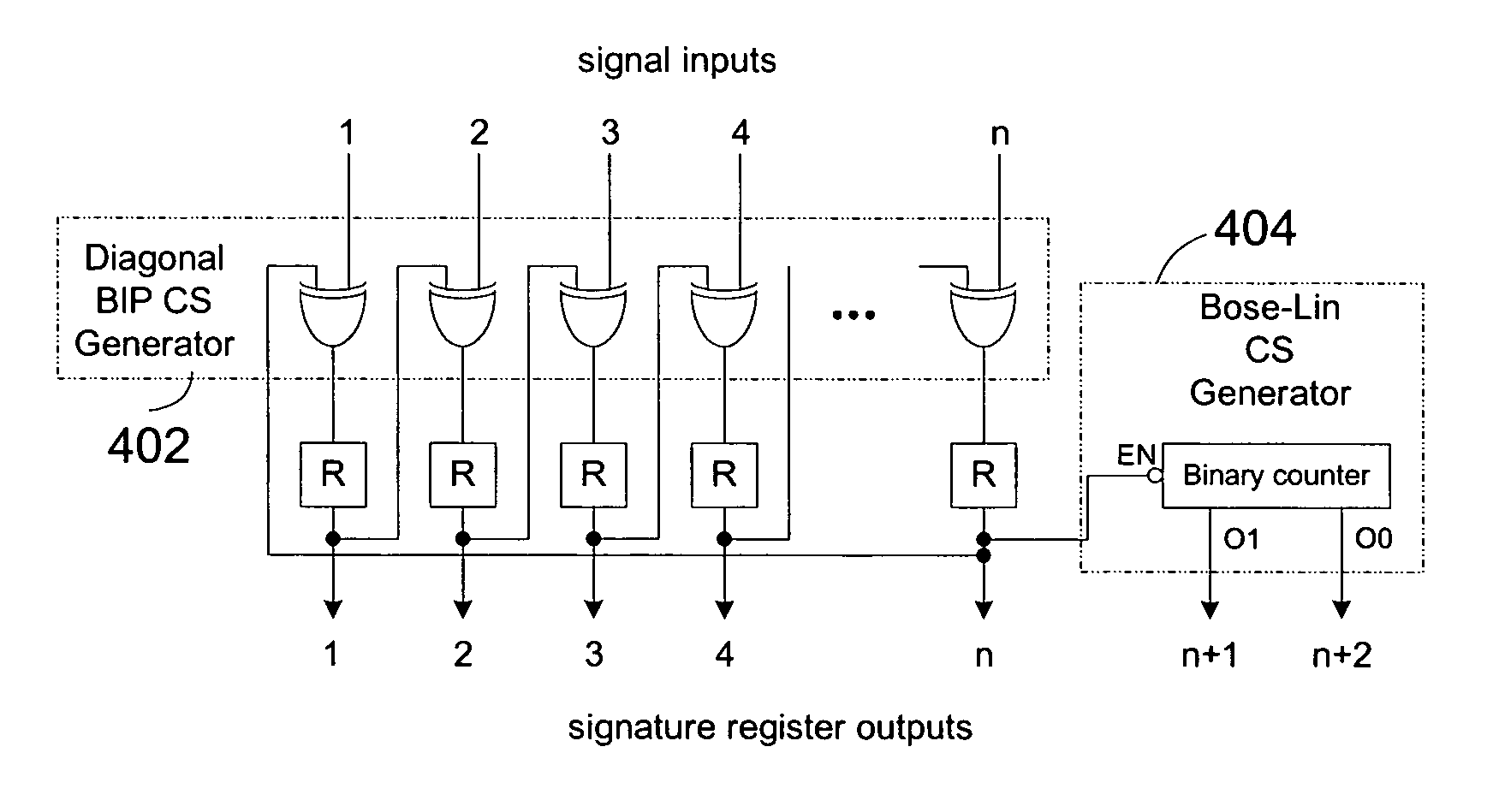
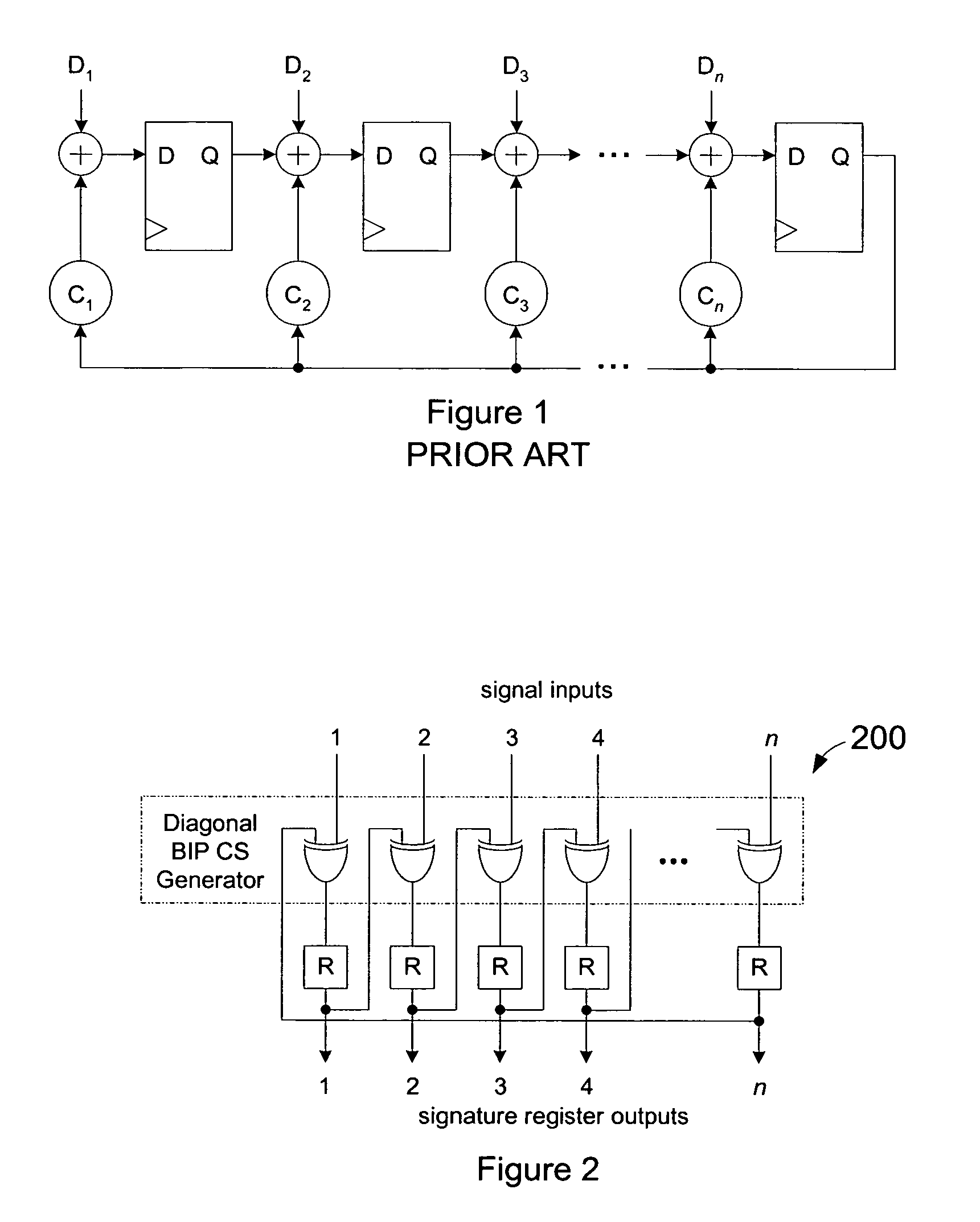
[0014]One embodiment includes a signature circuit in a diagonal bit-interleaved parity (BIP) configuration. Advantageously, each of the outputs from a signature register is provided as an input to one input stage of another register. In one embodiment, an output from each register is provided as an input to one XOR gate coupled to an input of one other register for determining the next state for the signature circuit. This reduces the load on a single register of the signature register.
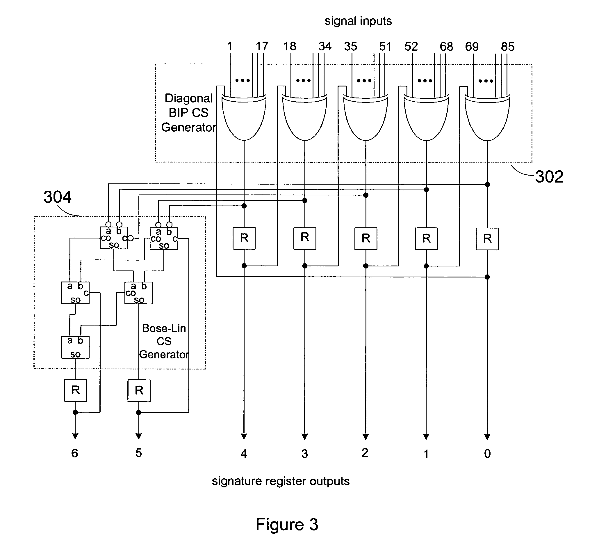
[0015]One embodiment includes a signature circuit that generates a signature based upon the application of a first type of check symbol code or error detection code, where the first type of code is the result of a form of bit-interleaved parity (BIP) and applies a second type of check symbol code, such as a weight-based code, different from the first type of check symbol code as a check of the results of the first code. In one embodiment, the second type of check symbol code corresponds to a Bose-Lin check symbol (CS) code. For the same number of signature register bits, the combination of multiple check symbol codes of varying types advantageously provides fault detection that exceeds the capabilities of either fault detection code by itself.

Problems solved by technology

Generally, the greater the complexity of this operation, the better the fault coverage.
More complex operations, however, can place limits on the speed at which the test vectors can be run.
For example, each increase in the depth of the logic used to generate a new Multiple Input Signature Register (MISR) value increases the propagation delay to the input of the MISR's register.
The can result in a decreased yield of otherwise good ICs due to faults occurring within the MISR.
Of course, larger MISR circuits also increase the die size of the IC, which also impacts cost.
One disadvantage to this approach is that the register driving the logic gates for the generator polynomial is loaded relatively heavily, which can slow down the rate at which the signature circuit operates.

Method used


Image

  • Systems and methods for signature circuits
  • Systems and methods for signature circuits
  • Systems and methods for signature circuits

Examples


example applications and embodiments

[0054]FIG. 6 illustrates an example of an application for an embodiment of the invention. In this example, the signature circuit is used to monitor an internal bus in a system-on-chip integrated circuit. The signature circuit monitors the states of the address and data buses, and their associated control signals, for an embedded processor. The signature circuit should be capable of detecting any faults on these bus and control lines, and should also be able to detect any faults within the processor, or other circuits with which it communicates over the bus, that result in at least one different or unexpected value appearing on the bus during the course of the test. Appropriately written test vectors should lead to such different values appearing on the bus for faulty circuits. In the illustrated application, there is no need to have the signature circuit contain fewer bits than the number of bits in the data bus, which is typically the same as the internal register width.

[0055]As il...


PUM


Abstract

Signature circuits are used during testing of an integrated circuit. Test vectors are applied as inputs to a circuit under test. A signature circuit stores a “signature” for the circuit under test based on a combination of signals from the circuit under test in response to test vectors and a previous stored state of the signature register. The value contained in the signature register at the end of the test is the signature. A fault-free circuit generates a particular signature for the applied test vectors. Faults can be determined by detecting variances from the expected signature. In one embodiment, the signature circuit uses a combination of two error detection codes.

Description

RELATED APPLICATION[0001]This application claims the benefit under 35 U.S.C. § 119(e) of U.S. Provisional Application No. 60 / 558,713, filed Apr. 1, 2004, the entirety of which is hereby incorporated by reference.BACKGROUND[0002]1. Field of the Invention[0003]The present invention is related to the testing of integrated circuits (ICs), including IC built in self tests (BISTs).[0004]2. Description of the Related Art[0005]Signature circuits are frequently used for detecting faults in integrated circuits. Test vectors are applied as test inputs to a circuit under test (CUT) or device under test (DUT). The monitored signals of the CUT are provided as inputs to a signature circuit. A conventional approach is to combine the monitored signals from the CUT with a stored value of the signature register (a “current” value) to create a new signature register value for each test vector is applied to the CUT. At the end of the set of test vectors, the contents of the signature register (i.e., the...

Claims


Application Information

Patent Timeline
IPC IPC(8): G01R31/28
CPCG01R31/31703
Inventor GORSHE, STEVEN SCOTT
Owner MICROSEMI STORAGE SOLUTIONS
Learn More