
Fluid bed granulation process

a technology of granulation process and flue bed, which is applied in the direction of crystal growth process, lighting and heating apparatus, applications, etc., can solve the problems of inability to control the granulation of final product, inability to achieve the effect of reducing the number of granules, and increasing the number of operating costs

Active Publication Date: 2008-10-21
CASALE SA
View PDF13 Cites 5 Cited by
  • Summary
  • Abstract
  • Description
  • Claims
  • Application Information

AI Technical Summary

Benefits of technology

The present invention is a fluid bed granulation process that aims to overcome the drawbacks of prior art. The process involves a cyclical process where each granule is formed and grown in the same fluid bed for a predetermined number of cycles. This allows for better control over the dimensions of the final granules. The process is controlled by controlling the execution time of each operational cycle. The invention provides a granulation process with improved functional characteristics.

Problems solved by technology

Among such drawbacks, the most important ones include the substantial inability to control the final product granulometry between predetermined values, and the elevated operating costs.
Furthermore, the first drawback involves classification and screening operations of the produced granules, the always considerable waste of granules of unacceptable size (too big or too little), the recovery operations of such waste and its recycle upstream to the granulation process.

Method used


Image

  • Fluid bed granulation process
  • Fluid bed granulation process
  • Fluid bed granulation process

Examples


Embodiment Construction

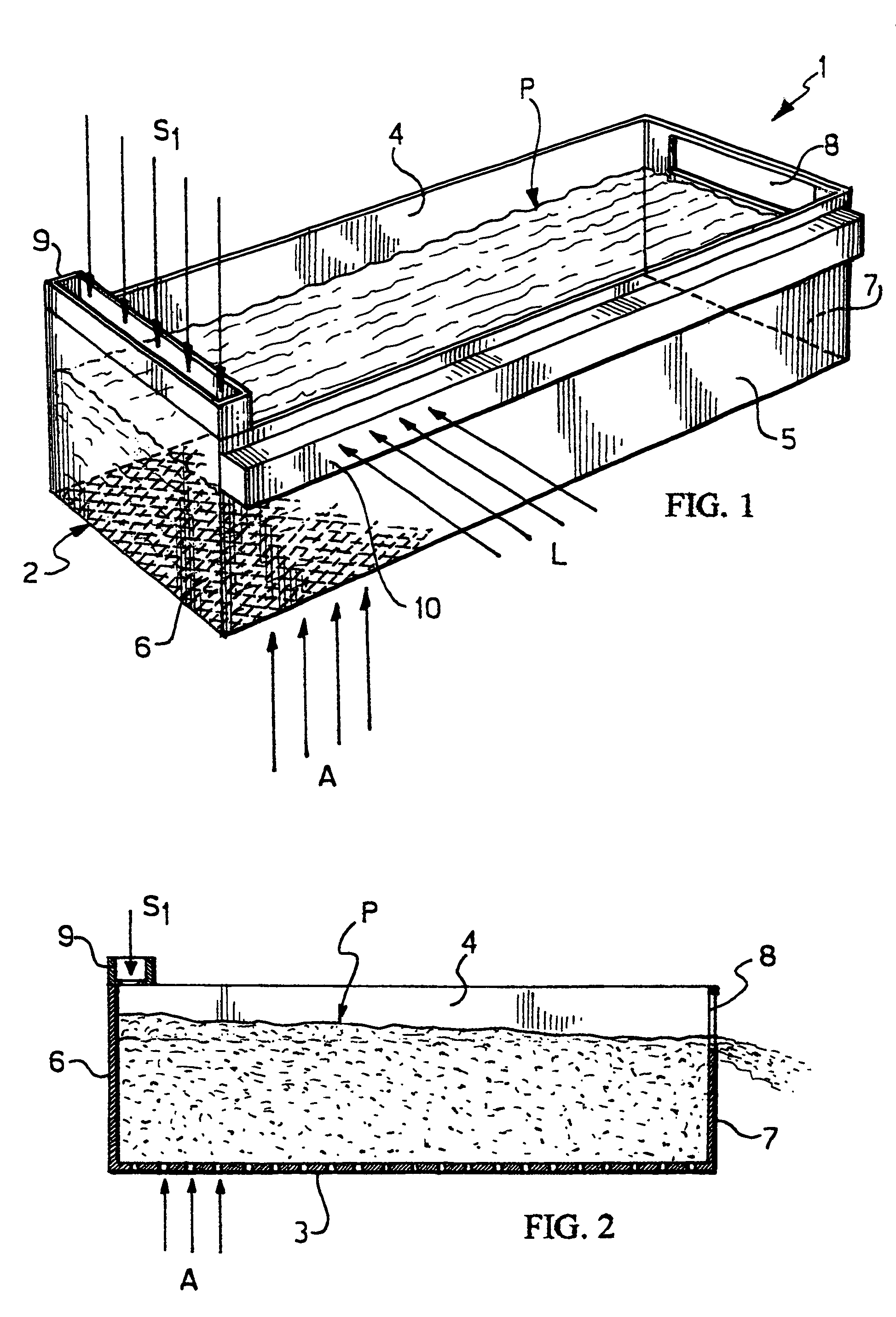
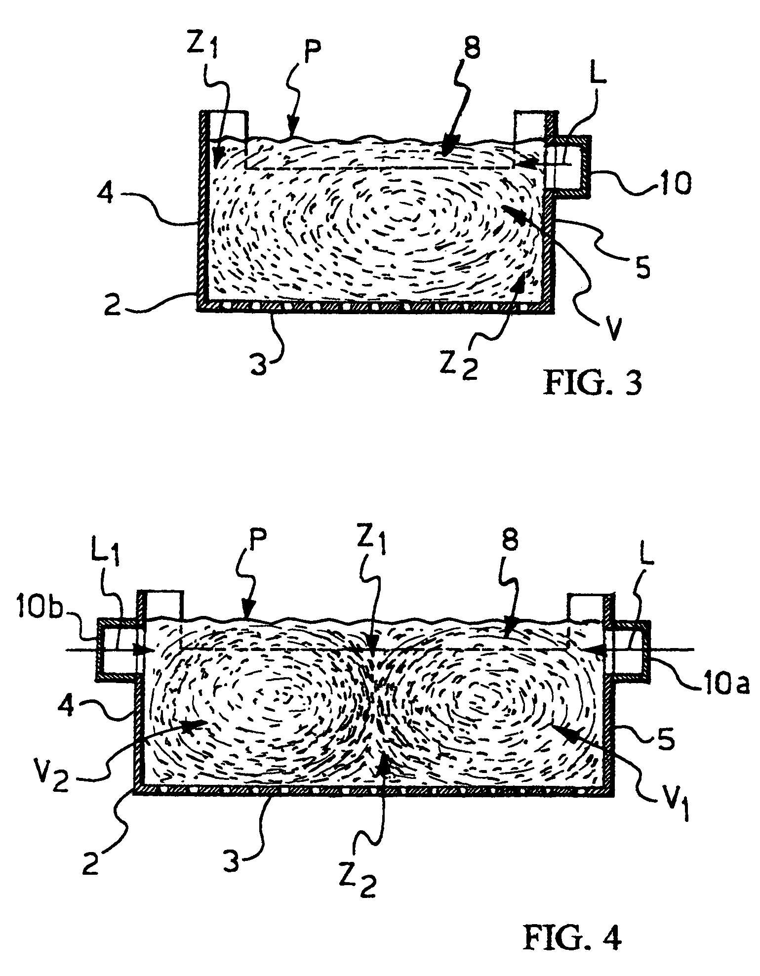
[0021]With reference to FIGS. 1, 2 and 3, a fluid bed granulator according to the present invention, indicated as a whole with 1, comprises a container 2, represented open at the top, of substantially parallelepiped shape, of rectangular section, in which a fluid bed is intended to be obtained, as will result from the prosecution of the description.

[0022]Said container 2 has a bottom 3, permeable to gas, for example made up of a perforated element, situated between two long opposite side walls 4, 5 and two short opposite side walls 6, 7. In the rest of the description, the short side wall 6 is also called: head wall of granulator 1, whereas the opposite wall 7 is also called: discharge wall of the (granulated) final product. This because the wall 7 is provided with a discharge opening 8 for the final granules; said discharge opening 8 is essentially a weir, and is preferably extended to all the width of wall 7 and to a height on bottom 3, predetermined according to the thickness of ...


PUM

PropertyMeasurementUnit
diameteraaaaaaaaaa
speedaaaaaaaaaa
speedaaaaaaaaaa

Abstract

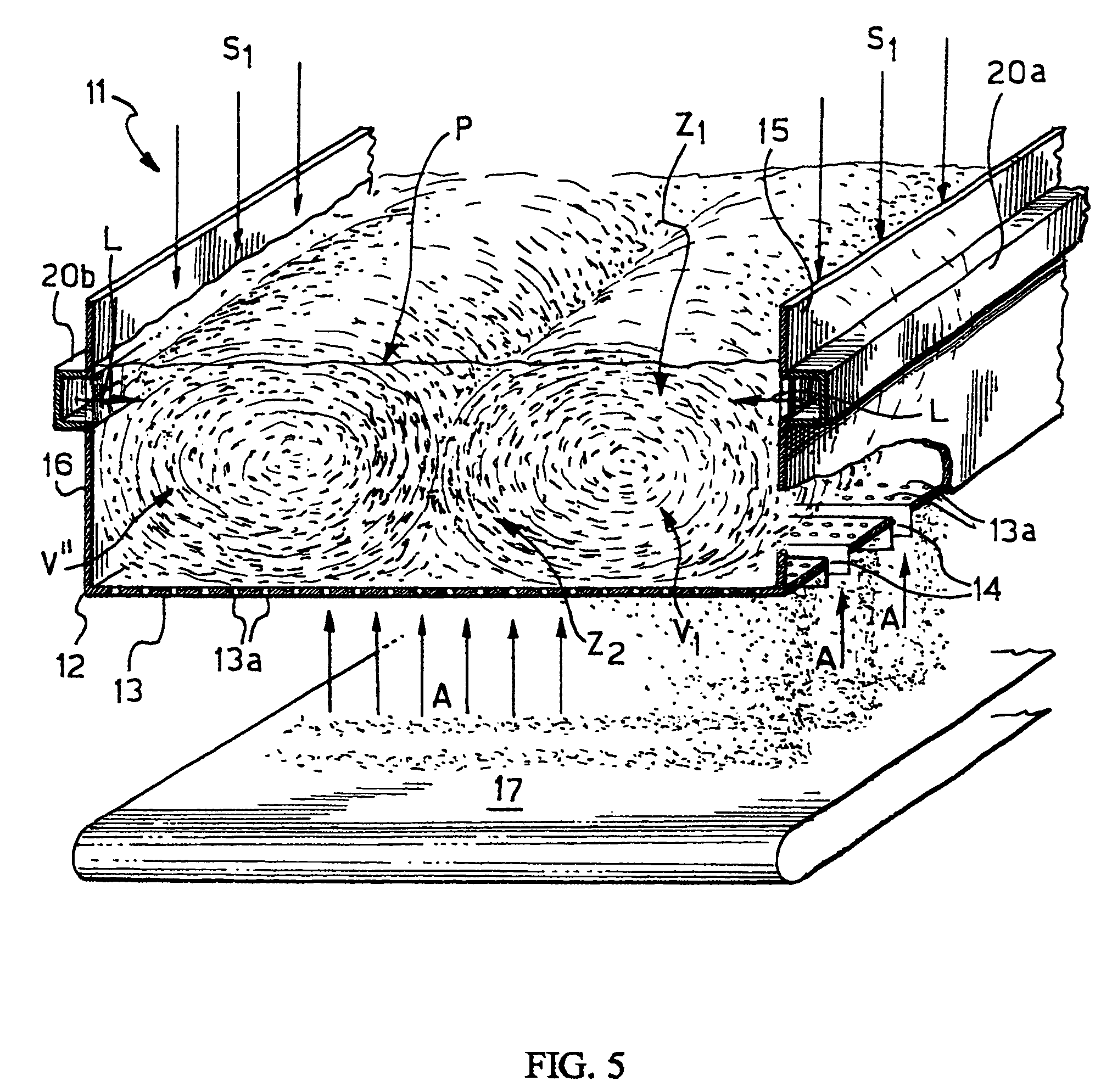
In order to produce granules granulometrically polidispersed in a very little range, a fluid bed granulation process of the type comprising the steps of preparing a fluid bed of seeds (S1) of the substance to be granulated, having a free surface (P) substantially horizontal; and feeding a continuous flow (L) of a fluid comprising a growth liquid, provides in the fluid bed for a continuous vortex (V) with a substantially horizontal axis, in which an upper zone (Z1) of seeds wetting and evaporation of possible solvent contained in the flow (L) and a lower zone (Z2) of solidification / consolidation of the growth liquid are identified.

Description

FIELD OF APPLICATION[0001]In its most general aspect the present invention relates to a fluid bed granulation process of a suitable substance like, for example (not limiting), urea, ammonium nitrate, ammonium chloride and other similar substances susceptible to be granulated.[0002]Particularly, this invention concerns a fluid bed granulation process, where granules of a chosen substance are obtained through continuous growth (of both volume and mass) of granule's seeds of that substance, continually fed in said fluid bed, simultaneously with a flow of a suitable growth substance in the liquid state.[0003]In the following description and attached claims, the expression: “granule's seed of a chosen substance” is generally meant to indicate particles of the substance to be granulated being equal or less than about 1.5 mm in diameter. Furthermore, to simplify, the term “seeds” will be used to indicate the granule's seeds.[0004]The growth substance is of the same nature of the substance ...

Claims


Application Information

Patent Timeline
Patent Type & Authority Patents(United States)
IPC IPC(8): C30B17/00B01J2/16B01J8/18
CPCB01J2/16B01J8/1818B01J2219/1923
Inventor BEDETTI, GIANFRANCO
Owner CASALE SA
Learn More