Assay devices having detection capabilities within the hook effect region

a technology of detection capability and hook effect, which is applied in the direction of material analysis by observing the effect of chemical indicators, instruments, biomass after-treatment, etc., can solve the problems of inability to detect and many conventional lateral flow assays encounter significant inaccuracy

Active Publication Date: 2008-10-21
KIMBERLY-CLARK WORLDWIDE INC
View PDF157 Cites 17 Cited by
  • Summary
  • Abstract
  • Description
  • Claims
  • Application Information

AI Technical Summary

Problems solved by technology

Despite the benefits achieved from these devices, many conventional lateral flow assays encounter significant inaccuracies when exposed to relatively high analyte concentrations.
Because the uncomplexed analyte is not labeled with a probe, it cannot be detected.

Method used


Image

  • Assay devices having detection capabilities within the hook effect region
  • Assay devices having detection capabilities within the hook effect region
  • Assay devices having detection capabilities within the hook effect region

Examples


example 1

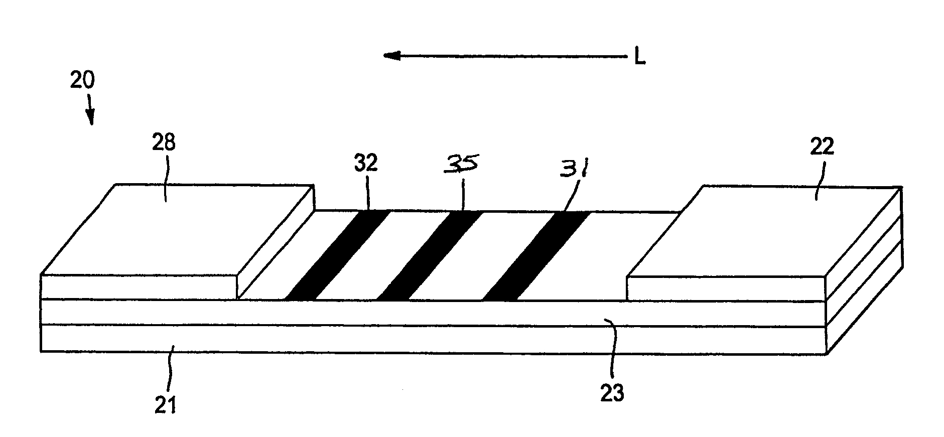
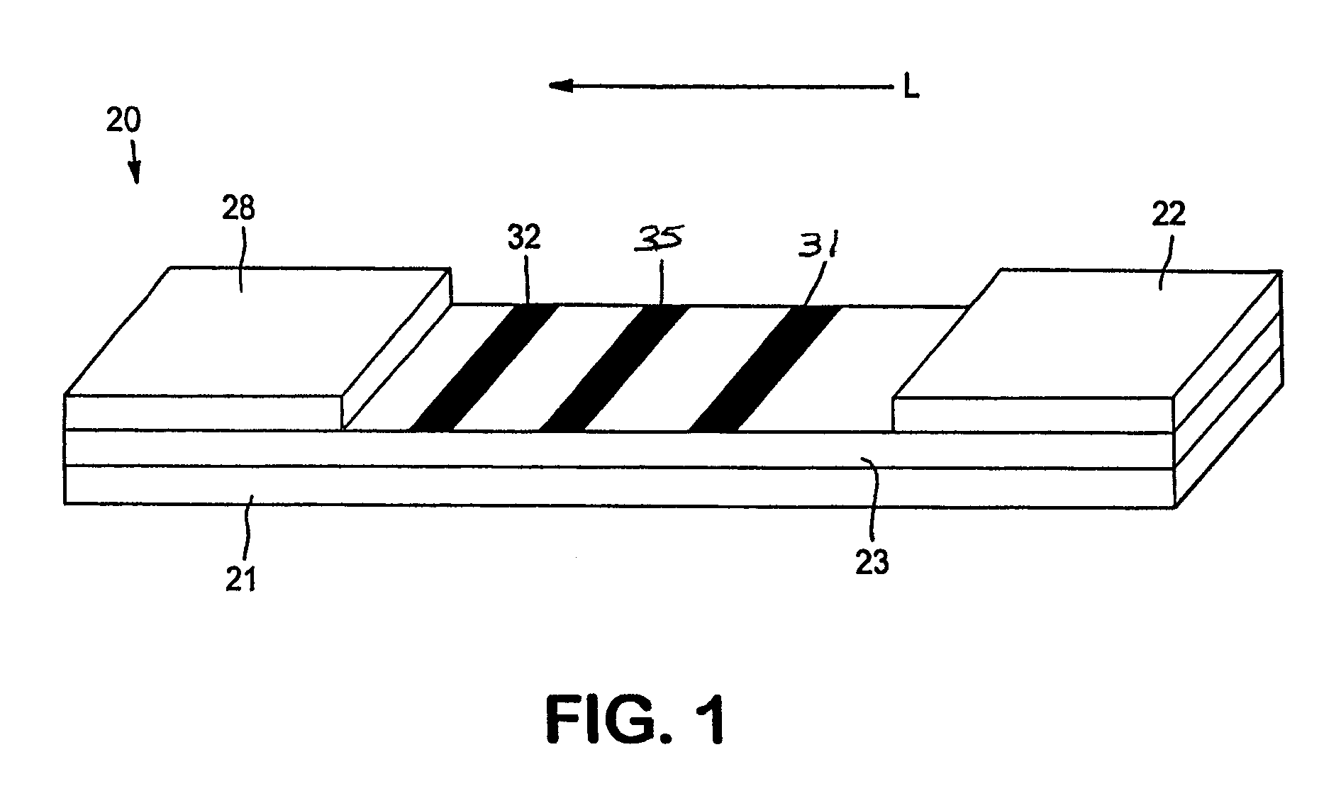
[0076]The ability to form a lateral flow assay device was demonstrated. A nitrocellulose porous membrane (HF 120 from Millipore, Inc.) having a length of approximately 30 centimeters was laminated onto supporting cards. Monoclonal antibody for C-reactive protein was immobilized on the porous membrane to form a detection zone. The antibody was obtained from BiosPacific, Inc. (Catalog #A58040136P) and had a concentration of 1 milligram per milliliter. CRP antigen was immobilized on the porous membrane to form an indicator zone. The antigen was obtained from Biogenesis Inc. of Kingston, N.H., and had a concentration of 2.78 milligrams per milliliter. Goldline™ (a polylysine solution obtained from British Biocell International) was striped onto the membrane to form a control zone. The indicator zone was positioned between the detection zone and the control zone. A cellulose wicking pad (Millipore Co.) was laminated with one end (closer to the control zone) of the membrane. The membrane ...

example 2

[0078]Lateral flow devices were formed as described in Example 1, except that 2.23 milligrams per milliliter of goat anti mouse IgG (Fc) was used to form the control zone.

example 3

[0079]The ability to form a lateral flow assay device was demonstrated. A nitrocellulose porous membrane (HF 120 from Millipore, Inc.) having a length of approximately 30 centimeters was laminated onto supporting cards. Monoclonal antibody for C-reactive protein (BiosPacific, Inc., Catalog #A58040136P) in 0.1% trehalose aqueous solution was immobilized on the porous membrane to form a detection zone. CRP antigen was immobilized on the porous membrane to form an indicator zone. The antigen was obtained from Biogenesis Inc. of Kingston, N.H., and had a concentration of 2.78 milligrams per milliliter. Goat anti alkaline phosphatase (2.5 milligrams per milliliter, obtained from Fitzgerald Industries International, Inc. of Concord, Mass.) was striped onto the membrane to form a calibration zone. The indicator zone was positioned between the detection zone and the calibration zone. A cellulose wicking pad (Millipore Co.) was laminated with one end (closer to the control zone) of the membr...


PUM

PropertyMeasurementUnit
concentrationaaaaaaaaaa
sizeaaaaaaaaaa
optical densityaaaaaaaaaa

Abstract

A lateral flow assay device for detecting the presence or quantity of an analyte within a test sample is provided. The device utilizes multiple zones, one of which serves as an indicator of whether or not the analyte in the test sample is within the “hook effect” region. Based on this indication, a technique may be selected for correlating a measured signal intensity to an analyte concentration or range of concentrations. For example, when it is determined that the test sample falls outside the “hook effect” region, the analyte concentration may be determined using one portion of a dose response curve. On the other hand, when it is determined that the test sample falls within the “hook effect” concentration, the analyte concentration may be determined using another portion of the dose response curve. Alternatively, the sample may simply be diluted for re-performing the assay. The present inventor has discovered that such a detection technique may simply, quickly and accurately detect an analyte present at any concentration.

Description

BACKGROUND OF THE INVENTION[0001]Various analytical procedures and devices are commonly employed in flow-through assays to determine the presence and / or concentration of analytes that may be present in a test sample. For instance, immunoassays utilize mechanisms of the immune systems, wherein antibodies are produced in response to the presence of antigens that are pathogenic or foreign to the organisms. These antibodies and antigens, i.e., immunoreactants, are capable of binding with one another, thereby causing a highly specific reaction mechanism that may be used to determine the presence or concentration of that particular antigen in a biological sample.[0002]There are several well-known immunoassay methods that use immunoreactants labeled with a detectable component so that the analyte may be detected analytically. For example, “sandwich-type” assay formats typically involve mixing the test sample with detection probes conjugated with a specific binding member (e.g., antibody) f...

Claims


Application Information

Patent Timeline
Patent Type & Authority Patents(United States)
IPC IPC(8): G01N21/00C12M1/34C12M3/00C12Q1/00G01N15/06G01N21/03G01N21/75G01N21/76G01N30/02G01N33/53G01N33/543G01N33/566
CPCG01N33/54366G01N33/558Y10S436/807G01N33/543G01N33/54388
Inventor SONG, XUEDONGCHRISTOPHER, PAUL
Owner KIMBERLY-CLARK WORLDWIDE INC
Why Eureka
Try Eureka