Check patentability & draft patents in minutes with Patsnap Eureka AI!

Timing recovery apparatus and method

a timing recovery and time-recovery technology, applied in the direction of digital transmission, transmission, synchronisation signal speed/phase control, etc., can solve the problems of lock error, inability to perform the convergence for a large timing frequency and phase offset, and high hardware cost, so as to improve the symbol recovery performance of the whole receiver, prevent lock detecting error, and optimize the effect of symbol recovery

Inactive Publication Date: 2008-10-21
LG ELECTRONICS INC
View PDF12 Cites 2 Cited by
  • Summary
  • Abstract
  • Description
  • Claims
  • Application Information

AI Technical Summary

Benefits of technology

The solution prevents lock errors, achieves faster and more accurate convergence, and optimizes symbol recovery performance by automatically selecting the final gain based on timing deviation existence, reducing hardware costs and improving convergence speed.

Problems solved by technology

Accordingly, the conventional lock detector has a drawback in that a hardware cost is very much paid for the variance calculation, and since the variance is different depending on the channel state after the convergence, the fixed threshold value generates an erroneous lock signal, thereby causing a lock error.
The above lock error does not only extend a convergence time, but also makes it impossible to perform the convergence for a large timing frequency and phase offset.
Of course, an appropriate threshold value is obtained by using a SNR calculator, but there is a drawback in that the convergence time of the symbol synchronizer is lengthened as long as a calculation time of the SNR calculator to make it possible to provide a weak remain characteristic, but to make it impossible to provide the convergence characteristic of the fast synchronization capture, thereby preventing the lock detector from performing its function in orderly fashion.
Further, the conventional timing lock detector, which accumulates and processes a spontaneous symbol error for a predetermined duration, has a drawback in that at the time of the existence of a symbol timing deviation, the timing deviation is minutely generated for a duration larger than the process duration of the timing lock detector, thereby making it impossible to detect the timing deviation.
At this time, a method of increasing the process duration of the conventional timing lock detector can be considered, but it has a drawback in that the delay of the lock judgment is caused to decrease a convergence speed of the receiver.

Method used


Image

  • Timing recovery apparatus and method
  • Timing recovery apparatus and method
  • Timing recovery apparatus and method

Examples


Embodiment Construction

[0067]Reference will now be made in detail to the preferred embodiments of the present invention, examples of which are illustrated in the accompanying drawings. Wherever possible, the same reference numbers will be used throughout the drawings to refer to the same or like parts.

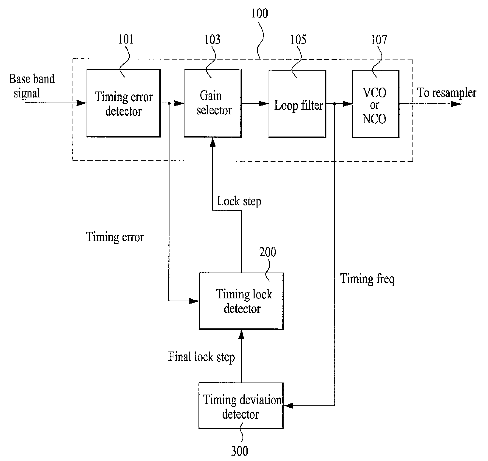
[0068]FIG. 4 is a block diagram illustrating a timing recovery apparatus having a timing lock detector and a timing deviation detector according to the present invention.

[0069]As shown in FIG. 4, the inventive timing recovery apparatus includes a symbol synchronizer 100 for determining a bandwidth of a timing recovery loop in a plurality of steps by a lock control signal outputted depending on a convergence degree; a timing lock detector 200 for judging the convergence degree to output the lock control signal; and a timing deviation detector 300 for detecting a timing deviation, which can be generated in the timing recovery process.

[0070]The symbol synchronizer 100 includes a timing error detector 101 for re...


PUM


Abstract

A timing recovery apparatus and method is provided. The apparatus includes: a symbol synchronizer for determining a bandwidth of a timing recovery loop by a lock step control signal, which is outputted depending on a convergence degree; a timing lock detector for judging the convergence degree to generate the lock step control signal; and a timing deviation detector for receiving a timing frequency signal outputted from the symbol synchronizer to detect the timing deviation.

Description

CROSS-REFERENCE TO RELATED APPLICATIONS[0001]Pursuant to 35 U.S.C. § 119(a), this application claims the benefit of earlier filing date and right of priority to Korean Application No. 10-2003-0086338, filed on Dec. 1, 2003, the contents of which are hereby incorporated by reference herein in their entirety.BACKGROUND OF THE INVENTION[0002]1. Field of the Invention[0003]The present invention relates to a timing recovery, and more particularly, to a timing recovery apparatus and method for detecting a timing lock and deviation for a timing recovery of a digital broadcasting receiver.[0004]2. Discussion of the Related Art[0005]Generally, since a symbol synchronization block of a Quadrature Amplitude Modulation (QAM) receiver, which is selected as a transmission standard of a digital TV cable channel, generates a clock of a symbol string, it is called a clock synchronizer or clock generator.[0006]An object of symbol synchronization is to right and accurately estimate a symbol transition...

Claims


Application Information

Patent Timeline
Patent Type & Authority Patents(United States)
IPC IPC(8): H04L7/00H03D3/24H04N7/015H04L7/033H04L7/10H04L27/38
CPCH04L7/033H04L7/10H04L27/38H04N7/015
Inventor LEE, TAE WON
Owner LG ELECTRONICS INC
Features
  • R&D
  • Intellectual Property
  • Life Sciences
  • Materials
  • Tech Scout
  • Unparalleled Data Quality
  • Higher Quality Content
  • 60% Fewer Hallucinations
Learn More