Liquid-repellent member, nozzle plate, liquid-jet head using the same, and liquid-jet apparatus

a liquid-repellent member and nozzle plate technology, applied in the field of liquid-repellent members, liquid-repellent parts, liquid-repellent parts, and liquid-repellent apparatuses, can solve the problems of high alkali resistance, misinterpretation of contact angle values, and inability to print in a predetermined spot, so as to achieve remarkable improvement in the characteristics of ejecting liquid droplets

Inactive Publication Date: 2008-10-28
SEIKO EPSON CORP
View PDF8 Cites 11 Cited by
  • Summary
  • Abstract
  • Description
  • Claims
  • Application Information

AI Technical Summary

Benefits of technology

[0011]In the first aspect, the intensity ratio of ions highest detected in fluorocarbon-based fragment ions to silicon ions is grater than or equal to 10, when the fluorocarbon-based fragment ions and the silicon ions are detected by the Time-of-Flight Secondary Ion Mass Spectrometer (hereinafter referred to appropriately as “ToF-SIMS”). With this configuration, the liquid-repellent member has high liquid repellency, is excellent in liquid-repellent durability, and can thus maintain the liquid repellency over a long time period.
[0023]In the seventh aspect, it is possible to provide the liquid-jet apparatus having the liquid-jet head, in which characteristics of ejecting liquid droplets are remarkably improved.

Problems solved by technology

Thus, the adhered ink remaining on the ejecting surface causes a problem of making it impossible to perform printing in a predetermined spot.
Moreover, high alkali resistance is required for long-term use because ink is often alkaline.
Moreover, even if the contact angle is changed by contamination on the solid surface, when a level of the contamination is a trace and invisible, the contact angle value may be misinterpreted.
It has been difficult to stably supply a member having excellent liquid repellency and liquid-repellent durability.

Method used


Image

  • Liquid-repellent member, nozzle plate, liquid-jet head using the same, and liquid-jet apparatus
  • Liquid-repellent member, nozzle plate, liquid-jet head using the same, and liquid-jet apparatus
  • Liquid-repellent member, nozzle plate, liquid-jet head using the same, and liquid-jet apparatus

Examples


first embodiment

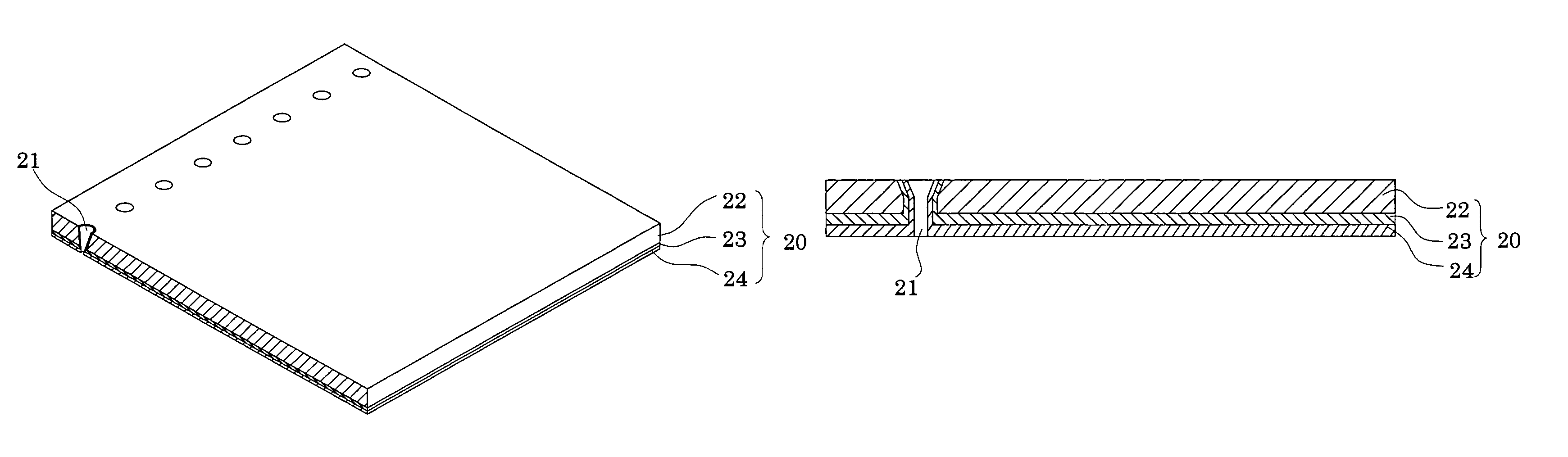
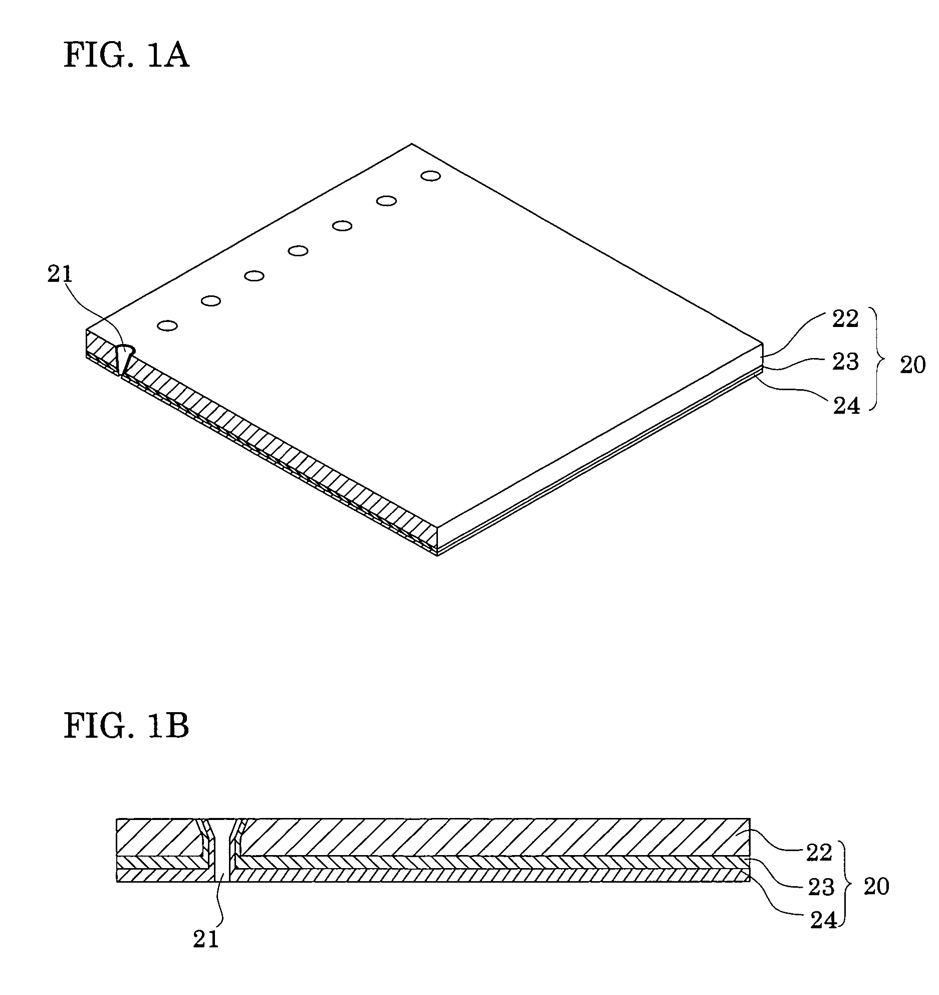
[0031]FIGS. 1A and 1B are a perspective view and a sectional view, respectively, of a nozzle plate according to a first embodiment of a liquid-repellent member of the present invention. A nozzle plate for use in a liquid-jet head is taken as an example of the liquid-repellent member of the present invention. As shown in FIG. 1A and FIG. 1B, a nozzle plate 20 includes a base 22 having nozzle orifices 21 formed therein, an underlayer film 23 provided on the surface of the base 22, and a liquid-repellent film 24 provided on the underlayer film 23. The underlayer film 23 and the liquid-repellent film 24 are provided on an outer surface of the base 22 and in the nozzle orifices 21. In FIG. 1B, there are shown the underlayer film 23 and the liquid-repellent film 24 formed so as to extend into the nozzle orifices 21. The underlayer film 23 and the liquid-repellent film 24, however, may be partially or wholly removed according to a purpose of the liquid-jet head. The underlayer film 23 is a...

second embodiment

[0053]FIG. 5 is an exploded perspective view showing the general configuration of a liquid-jet head according to the present invention. FIGS. 6A and 6B are a plan view and a sectional view, respectively, of the liquid-jet head shown in FIG. 5.

[0054]In a second embodiment, as shown in FIGS. 5 to 6B, a passage-forming substrate 10 is made of a plane oriented (110) single crystal silicon substrate. An elastic film 50 with a thickness of 0.5 to 2 μm, made of silicon dioxide, is formed on one surface of the passage-forming substrate 10. In the second embodiment, the elastic film 50 is an amorphous (or non-crystalline) film made of silicon oxide formed by thermal oxidation of the passage-forming substrate 10 made of the single crystal silicon substrate. The elastic film 50 has a surface in a flat state, keeping the surface state of the passage-forming substrate 10 as it is.

[0055]In the passage-forming substrate 10, a plurality of pressure generating chambers 12 partitioned by a plurality ...


PUM


Abstract

To provide a liquid-repellent member such as a nozzle plate having high liquid repellency and liquid-repellent durability, a liquid-jet head using the same, and a liquid-jet apparatus.A liquid-repellent member includes: an underlayer film which is provided on a surface of a base and contains silicon; and a liquid-repellent film which is provided on the underlayer film and is made of a silane coupling agent having a fluorocarbon group. In the liquid-repellent member, a intensity ratio of ions highest detected in fluorocarbon-based fragment ions to silicon ions is greater than or equal to 10 when the fluorocarbon-based fragment ions and the silicon ions are detected through measurement by a Time-of-Flight Secondary Ion Mass Spectrometer.

Description

[0001]The entire disclosure of Japanese Patent Application No. 2005-115021 filed Apr. 12, 2005 is expressly incorporated by reference herein.BACKGROUND OF THE INVENTION[0002]1. Field of the Invention[0003]The present invention relates to a liquid-repellent member, a liquid-jet head using the same, and a liquid-jet apparatus.[0004]2. Description of the Related Art[0005]A liquid-jet head has a nozzle plate in which a large number of fine eject holes (nozzle orifices) for ejecting a liquid therefrom are formed at minute spaced intervals. When ejected from the eject holes, ink may adhere to an ejecting surface. In this case, when ink next ejected comes into contact with adhered ink remaining on the ejecting surface, an ejecting path for the next ink droplets ejected is curved under influence of surface tension, viscosity or other properties of the adhered ink. Thus, the adhered ink remaining on the ejecting surface causes a problem of making it impossible to perform printing in a predet...

Claims


Application Information

Patent Timeline
Patent Type & Authority Patents(United States)
IPC IPC(8): B41J2/14B41J2/135
CPCB41J2/1433B41J2/1606B41J2/161B41J2/162B41J2/1623B41J2/1626B41J2/1646B41J2002/14241B41J2002/14419
Inventor NISHIJIMA, TATSUMI
Owner SEIKO EPSON CORP
Why Eureka
Try Eureka