

Resin structure and method for manufacturing resin structure
A manufacturing method and structure technology, which are applied in chemical instruments and methods, synthetic resin layered products, coatings, etc., can solve the problems of inability to obtain liquid repellency, limited liquid repellency, etc., to improve the liquid repellency function, maintain Liquid repellency, stabilizing effect
- Summary
- Abstract
- Description
- Claims
- Application Information
AI Technical Summary
Problems solved by technology
Method used
Image

Examples
Embodiment 1
[0145] (1) film
[0146] A film having a thickness of 100 μm was used, consisting of a polymer mainly composed of polypropylene (melting point: 144° C., glass transition temperature: −20° C.).
[0147] (2) Mold
[0148] The surface of the stainless steel plate is coated with a material mainly composed of Ni with a thickness of about 100 μm. Then, a micropore structure with a diameter of about 0.3 μm to 0.6 μm and a depth of about 7 μm to 10 μm is formed on the entire surface of the mold by laser processing to produce a mold. The area where micropores were formed accounted for 20% of the surface where micropores were formed.
[0149] (3) Forming device and conditions
[0150] About the device, use Figure 5 The forming device 50 is shown. The pressurizing unit 54 is a device that pressurizes with a hydraulic pump, and two pressurizing plates 57 and 58 are mounted on the upper and lower sides and connected to a heating device and a cooling device, respectively. The mold 53...
Embodiment 2
[0159] (1) film
[0160] The same film as in Example 1 was used.
[0161] (2) Mold
[0162] The same mold as in Example 1 was used.
[0163] (3) Forming device and conditions
[0164] A film was molded under the same conditions as in Example 1 except that the mold temperature during molding was 150° C. using the same molding apparatus 50 as in Example 1.
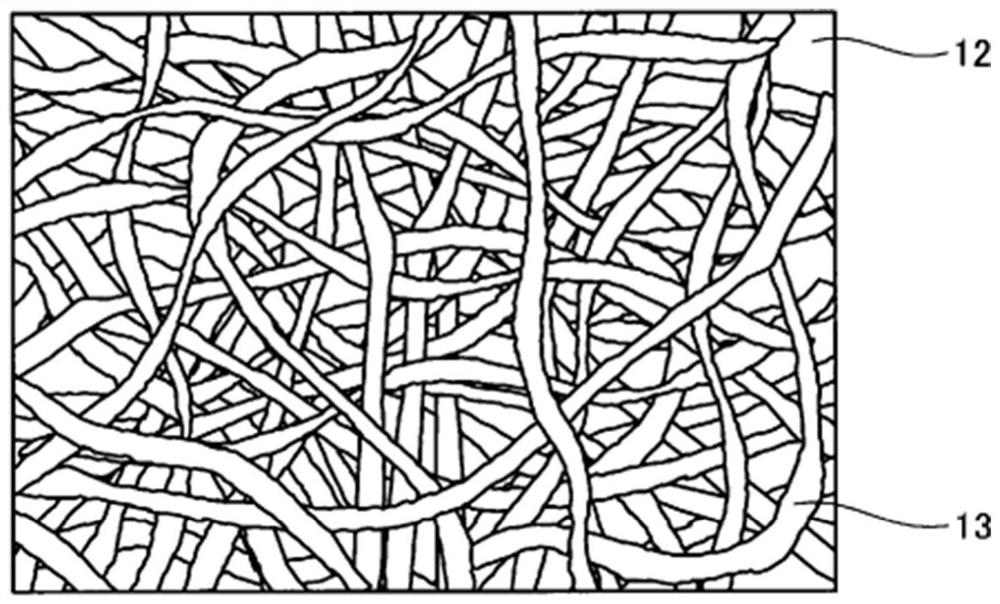
[0165] (4) Molding result
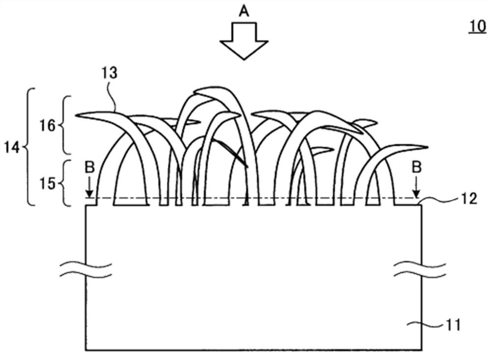
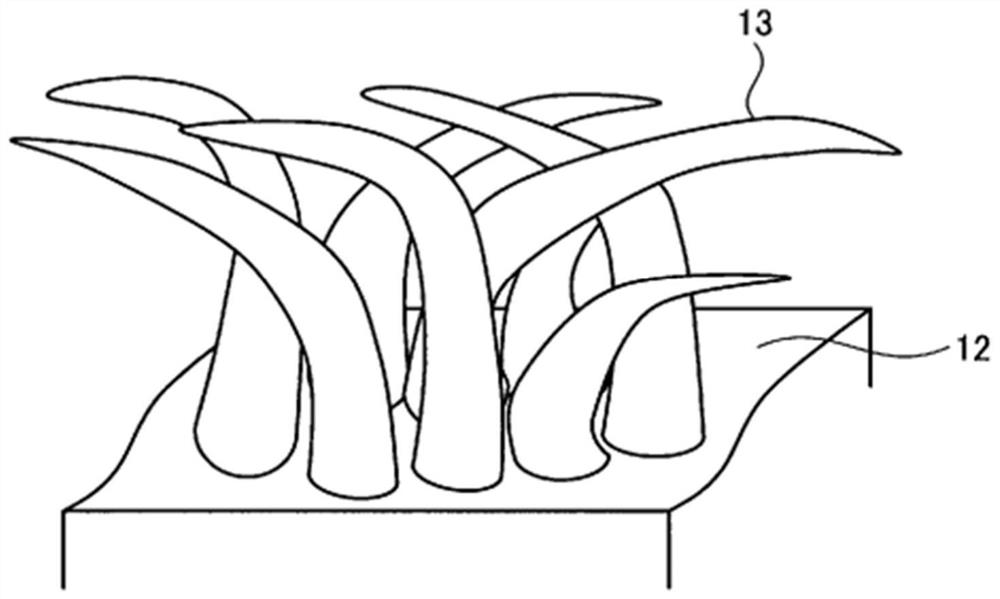
[0166] Figure 11 It is a photograph of the surface of the fiber-forming surface of the film 10 molded in Example 2 by a scanning electron microscope (Kinese VE-7800), Figure 12 It is a cross-sectional photograph of the thin film 10 molded in Example 2 with a scanning electron microscope (Keyence VE-7800). The molded film 10 is composed of a base layer 11 and a fiber layer 14 formed with a plurality of fibers 13 . The fiber layer 14 is composed of a substantially vertical portion 15 present on a side close to the base layer 11 and comprising fibers 13 substantially perpendicular to the sur...
Embodiment 3
[0172] (1) film
[0173] The same film as in Example 1 was used.
[0174] (2) Mold
[0175] The same mold as in Example 1 was used.
[0176] (3) Forming device and conditions
[0177] A film was molded under the same conditions as in Example 1 except that the mold temperature at the time of peeling was 80° C. using the same molding apparatus 50 as in Example 1.
[0178] (4) Molding result
[0179] Figure 13 It is a surface photograph of a scanning electron microscope (Keyence VE-7800) of the fiber formation surface of the film 10 molded in Example 3, Figure 14 It is a cross-sectional photograph of the thin film 10 molded in Example 3 with a scanning electron microscope (Keyence VE-7800). The molded film 10 is composed of a base layer 11 and a fiber layer 14 formed with a plurality of fibers 13 . The fiber layer 14 is composed of a substantially vertical portion 15 present on a side close to the base layer 11 and comprising fibers 13 substantially perpendicular to the ...
PUM
| Property | Measurement | Unit |
|---|---|---|
| diameter | aaaaa | aaaaa |
| thickness | aaaaa | aaaaa |
| melting point | aaaaa | aaaaa |
Abstract
Description
Claims
Application Information