Magnetic amplifier choke (magamp choke) with a magnetic core, use of magnetic amplifiers and method for producing softmagnetic cores for magnetic amplifiers

a technology of magnetic amplifier and choke, which is applied in the direction of core/yokes, electromagnets, magnetic materials, etc., can solve the problems of only achieving the volume of components, reducing the volume of transducer cores, and reducing the loss of magnetic reversal

Inactive Publication Date: 2008-10-28
VACUUMSCHMELZE GMBH & CO KG
View PDF10 Cites 20 Cited by
  • Summary
  • Abstract
  • Description
  • Claims
  • Application Information

AI Technical Summary

Benefits of technology

[0009]First, the windings' resistance should be as minimal as possible in order to reduce winding losses. This can be achieved by reducing the winding rate while concurrently increasing the conductor's cross-section. At the same time, this effects an increased changeover rejection of the transductor's core material and thus the magnetic reversal losses. However, a significant reduction of the transductor core volumes and thus the component volumes can only be achieved if the specific losses of the transductor's core materials are considerably reduced, or if very high magnetic reversal losses are permitted due to extremely high upper application limit temperatures.
[0014]The task of the present invention thus consists in providing a half-cycle transducer having an excellent switching behavior with operating frequencies ranging from 10 kHz to 200 kHz or higher, while having minimal cyclic magnetization losses at the same time. Furthermore, the magnetic cores used should have a rather high aging stability up to temperatures of at least 150° C. or more, and they should have a rather small magnetic core volume.

Problems solved by technology

First, the windings' resistance should be as minimal as possible in order to reduce winding losses. This can be achieved by reducing the winding rate while concurrently increasing the conductor's cross-section. At the same time, this effects an increased changeover rejection of the transductor's core material and thus the magnetic reversal losses. However, a significant reduction of the transductor core volumes and thus the component volumes can only be achieved if the specific losses of the transductor's core materials are considerably reduced, or if very high magnetic reversal losses are permitted due to extremely high upper application limit temperatures.
Secondly, the so-called induction excursion ΔBRS=BS−BR of remanence BR into saturation BS should be as negligible as possible, as the induction excursion ΔBRS signifies a tension-time area that cannot be regulated. The tension-time area, which is offered to the transductor for an adjustment to a maximum of power becomes increasingly smaller due to which a large tension-time area has an increasingly stronger effect due to ΔBRS. Enlarging the core geometry or the core volume can compensate this. This could entail increased cyclic magnetization losses, however. Since transductor cores with a rectangular hysteresis cycle have particularly high remanence values, they are therefore particularly well suited for transductor regulators with higher operating frequencies. Such rectangular characteristics can be created if the transductor core material has a uniaxial anisotropy KU parallel to the magnetic field H, which had been created by means of the core.
However, due to high losses the alloy examples that are shown in the embodiment of the invention in connection with the heat treatments for transductor cores, which are described there, indicate that they have not been optimized for a deployment with high frequencies.
Thus, the maximum possible operating frequencies are apparently limited to 150 kHz.
Furthermore, excessive losses and noises, which are created due to magnetic elastic vibrancies, can be expected.

Method used


Image

  • Magnetic amplifier choke (magamp choke) with a magnetic core, use of magnetic amplifiers and method for producing softmagnetic cores for magnetic amplifiers
  • Magnetic amplifier choke (magamp choke) with a magnetic core, use of magnetic amplifiers and method for producing softmagnetic cores for magnetic amplifiers
  • Magnetic amplifier choke (magamp choke) with a magnetic core, use of magnetic amplifiers and method for producing softmagnetic cores for magnetic amplifiers

Examples


first embodiment

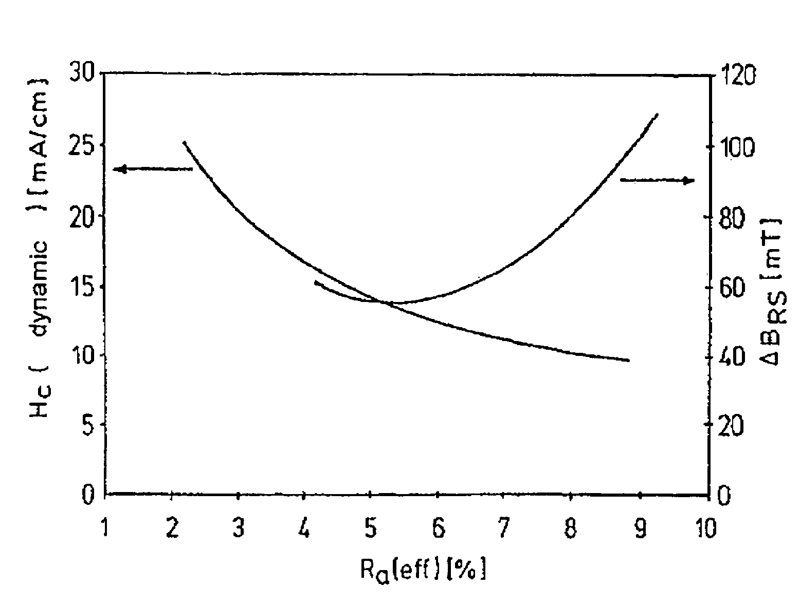
[0074]Particularly excellent physical results were obtained using a magnetic core, which was wound tension-free, with the dimensions 30×20×10 mm3 from the alloy Fe73.42Cu0.99Nb2.98Si15.76B6.85, whereby the effective roughness Ra (eff) of the band's surface was 4.5%. The mean band thickness was 20.7 μm.

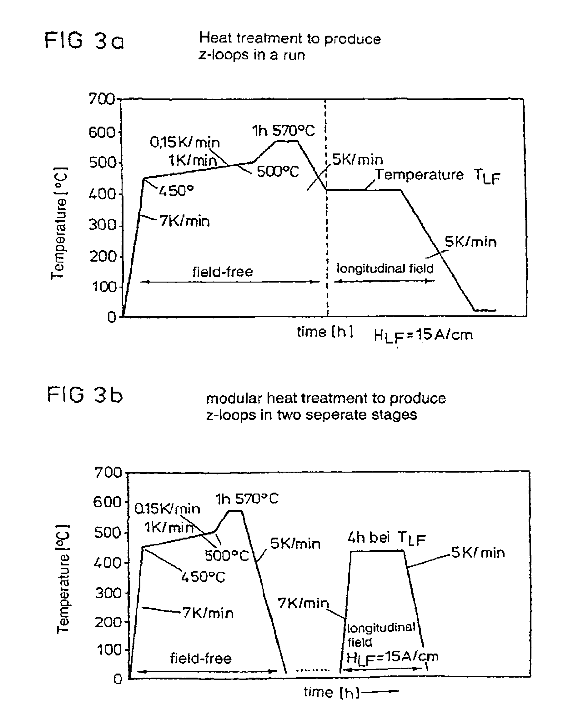
[0075]FIGS. 4a and 4b show the temperature / time profile of the deployed heat treatments. The magnetic cores were initially heated to a temperature of approximately 450° C. using a heating rate of 7 K / min. No magnetic field had been set up. The heating rate was subsequently delayed to approximately 0.15 K / min in order to avoid an undefined overheating of the magnetic core due to an exothermal heat development during the nanocrystallization process, which begins at that point. It was heated up to a temperature of approximately 500° C. using this relatively low heating rate of 0.15 K / min. Using a heating rate of 1 K / min it was heated to a final temperature plateau of 565° C.

[0076]The magn...

second embodiment

[0081]A magnetic core consisting of the same alloy compound and the same dimensions as in the first embodiment, and which was wound tension-free was used. However, a reduced longitudinal field temperature of approximately 315° C. was used to lower the cyclic magnetization losses Pfe for a shorter time of 2 hours. This heat treatment is shown in FIG. 5a. FIG. 5b shows the same heat treatment in modular form the main features of which were discussed in the first embodiment.

[0082]The cyclic magnetization losses Pfe, which resulted from a dwell time that had been reduced to 2 hours, and a lowered longitudinal field temperature of approximately 315° C. were only at 62 watt / kg at this point. The dynamic residual excursion ΔBRS, however, was increased to 137 mT. The transductor regulator's dead time, which is related thereto, was excessive thereafter, which is why the output voltage of 3.3 volt power supply unit output collapsed under a load of 10 watts while the 5 volt output, which was d...

third embodiment

[0083]The use of power barrier diodes including an increased recovery current during the transition into the locked direction enabled a well-defined increase of the coercive field strength of transductor regulators. A magnetic core consisting of the identical alloy compound as in the first embodiment and having the same dimensions was tempered to the maximum longitudinal anisotropy KU using a single phase heat treatment at a temperature of approximately 575° C. in a magnetic longitudinal field with a strength of HLF=30 A / cm. Thus, a very small residual excursion ΔBRS=25 mT was obtained, whereas the cyclic magnetization losses Pfe increased up to 160 watt / kg at 50 kHz / 0.4 T. To reduce the modulation while maintaining the tension / time area, the transductor core had to be enlarged to a dimension of 30×20×17 mm3 due to the excessive cyclic magnetization losses. The heat treatment which was applied is depicted in FIG. 6. However, independent of the recovery effect, such transductor types...


PUM

PropertyMeasurementUnit
frequencyaaaaaaaaaa
temperatureaaaaaaaaaa

Abstract

The invention relates to a transductor regulator with a magnetic core which is made up of a nanocrystalline alloy which is almost free of magnetorestriction. The core has as low cyclic magnetization losses as possible and as rectangular a hysterisis cycle as possible. Said alloy has the composition: FeaCobCucM′dSixByM″z, M′ representing an element from the group V, Nb, Ta, Ti, Mo, W, Zr, Hf or a combination of these and M″ representing an element from the group C, P, Ge, As, Sb, In, O, N or a combination of these and the following conditions applying: a+b+c+d+x+y+z=100%, with a=100%−b−c−d−x−y−z, 0≦b≦15, 0.5≦c≦2, 0.1≦d≦6, 2≦x≦20, 2≦y≦18, 0≦z≦10 and x+y>18. The inventive transductor regulators are particularly advantageously used in motor vehicle voltage supplies, rail power supplies or in aircraft power supplies.

Description

[0001]This application claims priory to German Application No. 100 45 705.3 filed on Sep. 15, 2000 and is a 371 of International Application No. PCT / EP01 / 10362 filed on Sep. 7, 2001, the entire contents of which are incorporated herein by reference.BACKGROUND[0002]1. Field[0003]Transductor choke with a magnetic core, use of transductor chokes and method for producing magnetic cores for transductor chokes.[0004]The invention relates to a transductor choke with a magnetic core, the deployment of transductor chokes as well as a method for producing magnetic cores for transductor chokes.[0005]2. Description of Related Art[0006]Switched power supply units using transductor regulators with clock frequencies between 20 kHz and 300 kHz are being progressively more deployed in ever more diversified applications as for instance in applications, which require voltages that are adjusted exactly to a maximum of power or currents despite quick load changes. They include e.g. switched power supply...

Claims


Application Information

Patent Timeline
Patent Type & Authority Patents(United States)
IPC IPC(8): H01F1/147H01F1/153C21D6/00C22C38/00H01F1/14H01F41/02
CPCH01F1/15308H01F1/15333H01F41/0226Y10T29/4902
Inventor GUNTHER, WULFKLINGER, ROMANLOGES, WERNERPETZOLD, JORG
Owner VACUUMSCHMELZE GMBH & CO KG
Why Eureka
Try Eureka