Focal plane array incorporating ultra-small resonant structures

a resonant structure and ultra-small technology, applied in the field of microelectromagnetic resonant detectors, can solve the problems of mircobolometers being limited by their response speed, cooled sensors offering greater sensitivity, and more expensiv

Active Publication Date: 2008-10-28
ADVANCED PLASMONICS
View PDF200 Cites 39 Cited by
  • Summary
  • Abstract
  • Description
  • Claims
  • Application Information

AI Technical Summary

Problems solved by technology

Cooled sensors offer greater sensitivity, but are more expensive because of the cost required to cool them.
Furthermore, mircobolometers are limited by their response speed.

Method used


Image

  • Focal plane array incorporating ultra-small resonant structures
  • Focal plane array incorporating ultra-small resonant structures
  • Focal plane array incorporating ultra-small resonant structures

Examples


Embodiment Construction

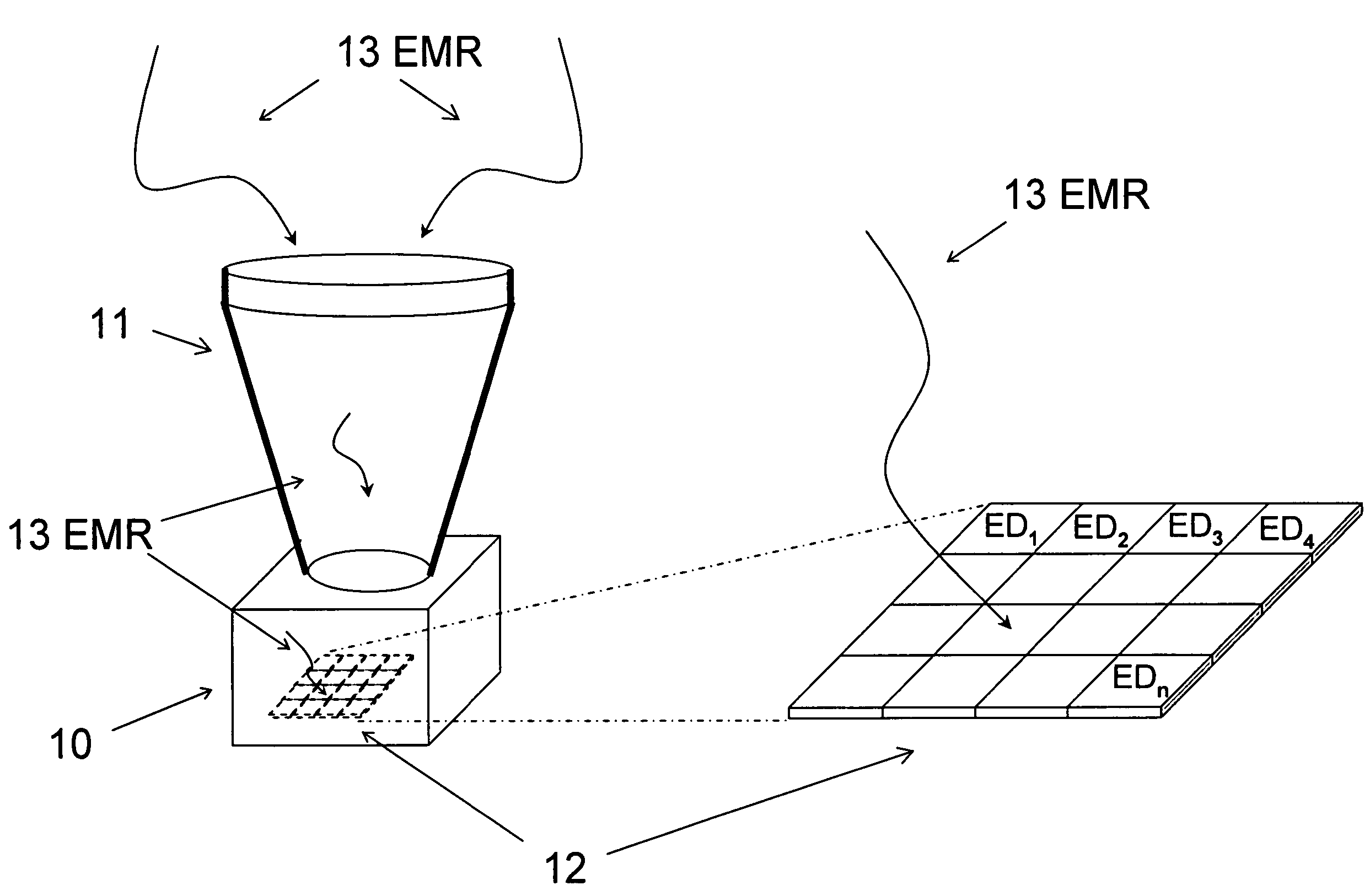
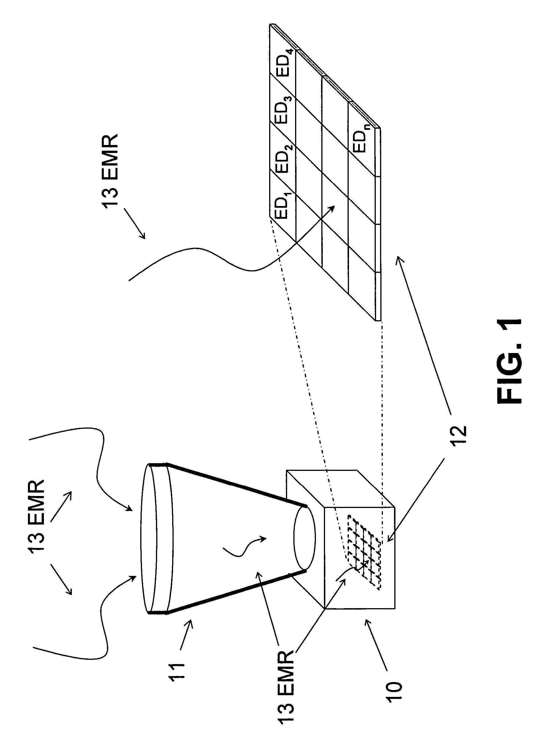
[0025]As shown in FIG. 1, an imaging device 10 that includes a lens system 11 and at least one Focal Point Array (FPA) 12 comprised of a plurality of micro-electromagnetic resonant detector cells, where each micro-electromagnetic resonant detector cell is denoted as ED1, ED2 . . . EDn. An enlarged view of the surface of the FPA 12 is shown to the right of the imaging device 10. EMR 13 is focused through the lens system 11 and is absorbed by the surface of the FPA 12. The structure set forth in FIG. 1 is intended to be exemplary only and is not intended to limit the ways in which a FPA can or might absorb EMR 13. It should be noted, that the FPA 12 may be capable of moving within the housing of the imaging device 10 e.g. the FPA 12 may be capable of rotating about an axis or tilting about an axis.

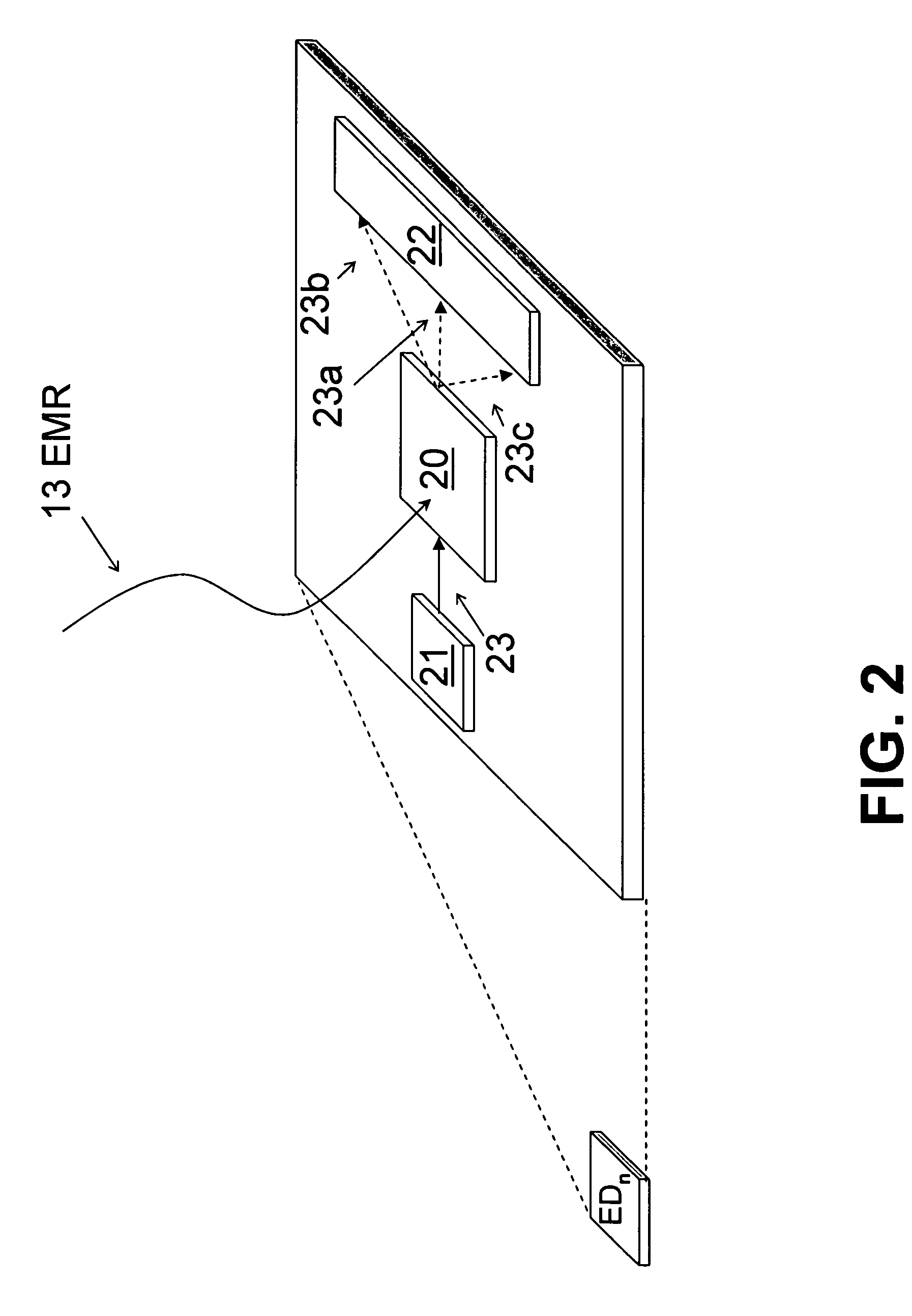
[0026]Each detector cell ED1-EDn includes a charged particle source, at least one detector and at least one ultra-small resonant structure. It should be noted that although the detectors cel...


PUM


Abstract

A focal plane array electromagnetic radiation detector includes an array of micro-electromagnetic resonant detector cells. Each micro-electromagnetic resonant detector cell may include an ultra-small resonant structure for receiving an electromagnetic wave and adapted to angularly modulate a charged particle beam in response to receiving an electromagnetic wave. Each micro-electromagnetic detector cell may include a detector portion that measures the angular modulation of the charged particle beam. The ultra-small resonant structure is designed to angularly modulate the charged particle beam according to a characteristic of the received electromagnetic wave.

Description

COPYRIGHT NOTICE[0001]A portion of the disclosure of this patent document contains material which is subject to copyright or mask work protection. The copyright or mask work owner has no objection to the facsimile reproduction by anyone of the patent document or the patent disclosure, as it appears in the Patent and Trademark Office patent file or records, but otherwise reserves all copyright or mask work rights whatsoever.CROSS-REFERENCE TO RELATED APPLICATIONS[0002]The present invention is related to the following co-pending U.S. patent applications which are all commonly owned with the present application, the entire contents of each of which are incorporated herein by reference:[0003]1. U.S. application Ser. No. 11 / 302,471, entitled “Coupled Nano-Resonating Energy Emitting Structures,” filed Dec. 14, 2005,[0004]2. U.S. application Ser. No. 11 / 349,963, entitled “Method And Structure For Coupling Two Microcircuits,” filed Feb. 9, 2006;[0005]3. U.S. patent application Ser. No. 11 / 2...

Claims


Application Information

Patent Timeline
Patent Type & Authority Patents(United States)
IPC IPC(8): H01J3/14
CPCB82Y15/00H01J25/00G01J3/12
Inventor GORRELL, JONATHANDAVIDSON, MARKMAINES, MICHAEL E.
Owner ADVANCED PLASMONICS
Why Eureka
Try Eureka