Inspection apparatus for inspecting a display module

a technology for inspecting apparatus and display modules, which is applied in the direction of electrical apparatus casings/cabinets/drawers, identification means, instruments, etc., can solve the problems of poor workability, inability to improve manufacturing efficiency, and inconvenience following, so as to achieve convenient movement and more usability

Inactive Publication Date: 2008-10-28
SHARP KK
View PDF14 Cites 0 Cited by
  • Summary
  • Abstract
  • Description
  • Claims
  • Application Information

AI Technical Summary

Benefits of technology

[0008]In view of the conventionally experienced inconvenience mentioned above, the present invention provides an inspection apparatus for inspecting a display module with which inspection apparatus, when a display module is mounted thereon, the display module is readily connected electrically to a power source and control circuitry, and thus with improved workability.
[0011]Specifically, the stage has a pair of stoppers for holding the display module by sandwiching the display module from the left-hand and right-hand side edges thereof, and the second connector is provided on one of those stoppers. This permits the display module to be held upright when mounted on the stage, and also ensures connection between the first and second connectors.
[0013]Advisably, the inspection apparatus is built as a movable handcart. This makes the inspection apparatus easy to move and thus more usable.

Problems solved by technology

However, the conventional housing rack causes the following inconvenience.
This results in poor workability, and thus makes improvement in manufacturing efficiency infeasible.

Method used


Image

  • Inspection apparatus for inspecting a display module
  • Inspection apparatus for inspecting a display module
  • Inspection apparatus for inspecting a display module

Examples


Embodiment Construction

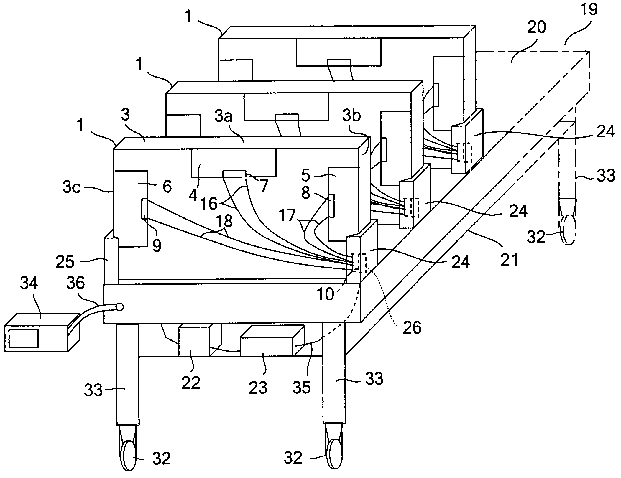
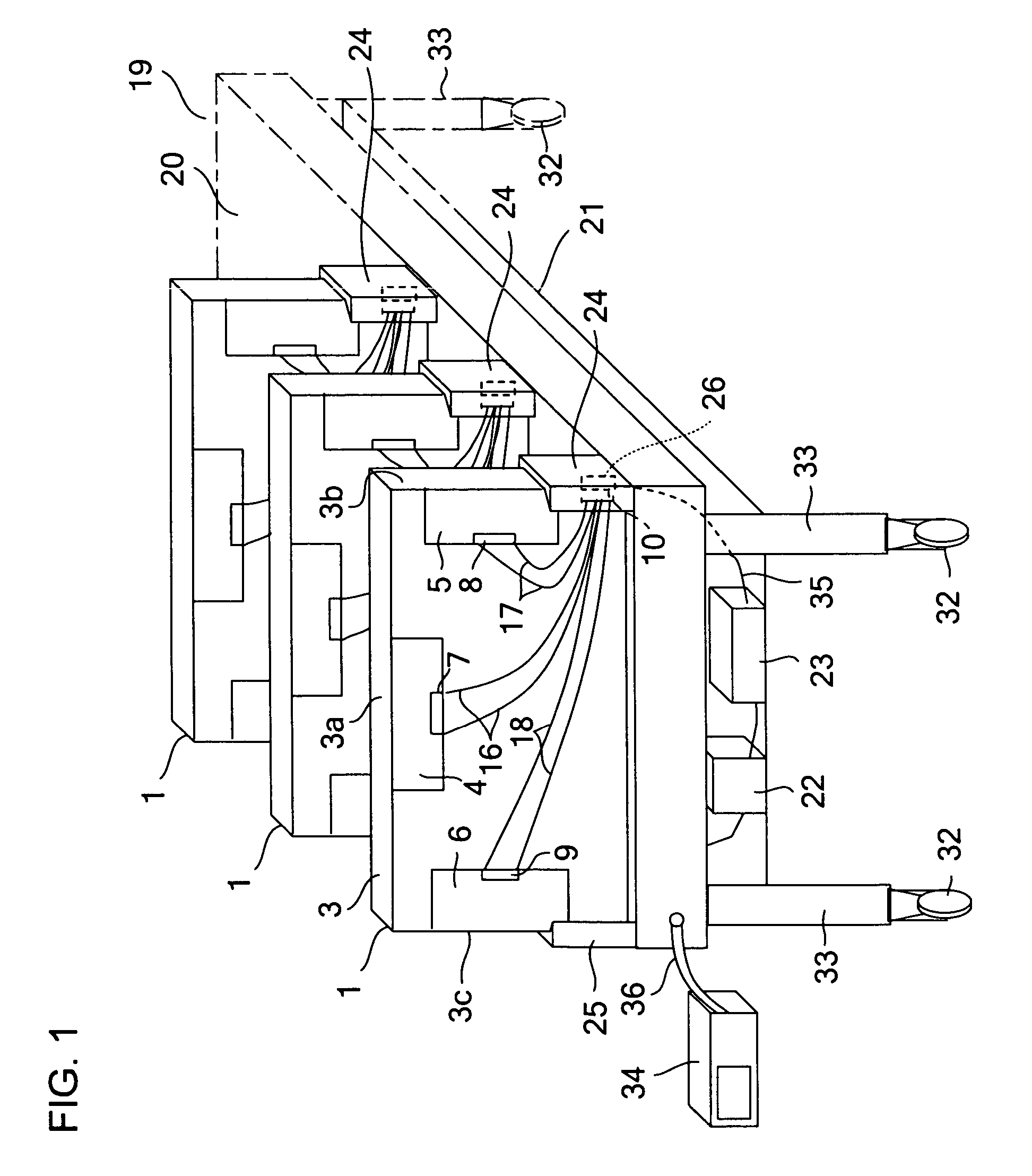
[0030]Hereinafter, an embodiment of the present invention will be described with reference to the accompanying drawings. The embodiment described below deals with an example in which an inspection apparatus for inspecting a display module is realized in the form of a transportable handcart. It should be understood, however, that the present invention is applicable to an inspection apparatus constructed in any other manner than specifically described below so long as it is of the type that is connected to a display module to control it; for example, an inspection apparatus according to the present invention may be realized in the form of, instead of a transportable handcart, a housing rack.

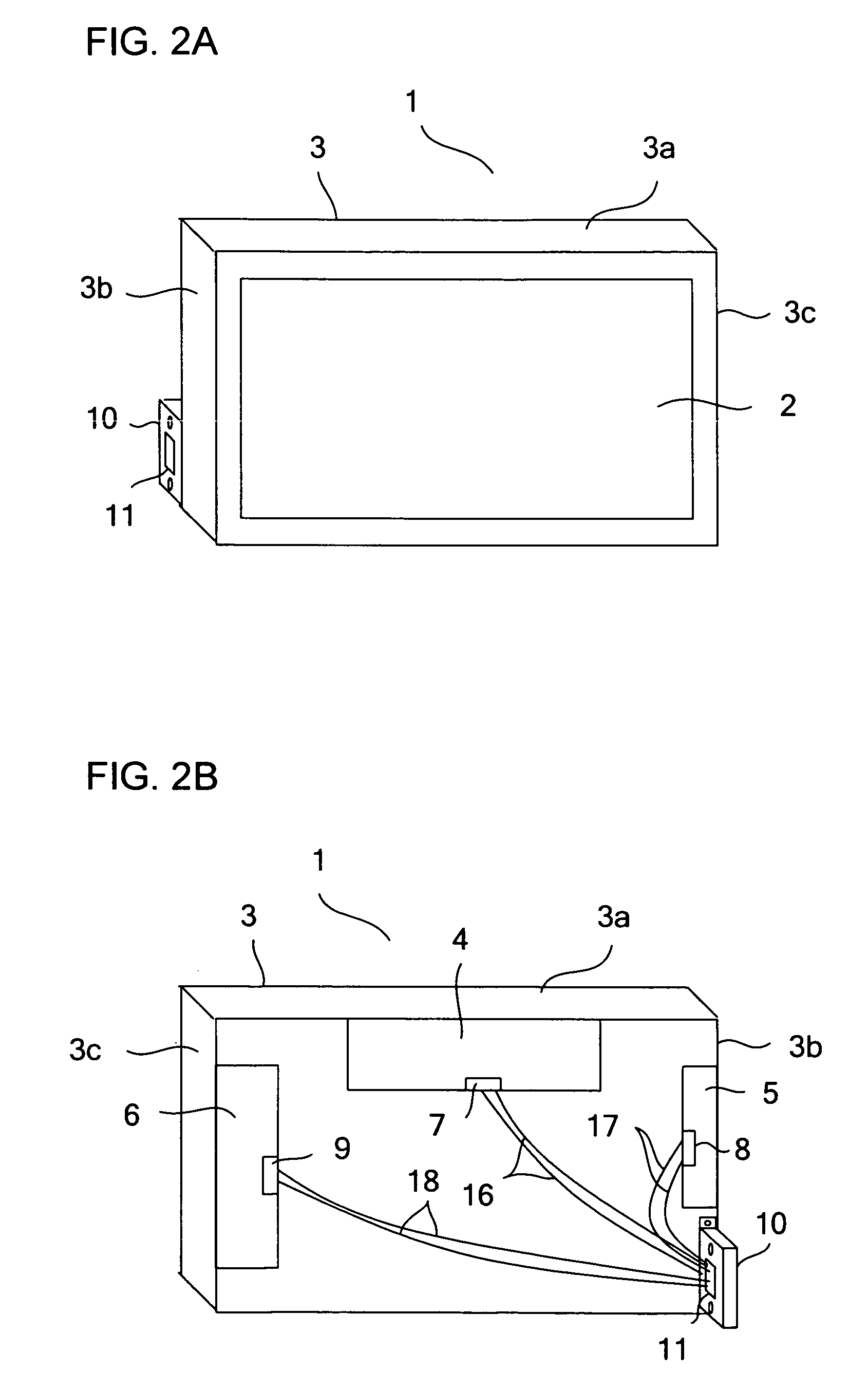
[0031]FIG. 1 is a perspective view showing a state in which display modules are mounted on an inspection handcart. FIG. 2A is a perspective front view of the display module, and FIG. 2B is a perspective rear view of the display module. As shown in FIG. 2A, the display module 1 includes: an active m...


PUM

PropertyMeasurementUnit
widthaaaaaaaaaa
inclination anglesaaaaaaaaaa
poweraaaaaaaaaa

Abstract

For inspecting a display module an inspection device is provided. There is a first connection having inputs for providing electric power and various signals needed to drive a display device. The display module can be mounted on the inspection device. There is a power supply for generating the electric power, a control circuit for generating the various signals, and a second connector having outputs of the power supply and the control circuit. When the display module is mounted on the inspection device, the first and second connectors are connected together, so the power supply and the control circuit can be electrically connected to the display module.

Description

[0001]This nonprovisional application claims priority under 35 U.S.C. § 119(a) on Patent Application No. 2003-201017 filed in Japan on Jul. 24, 2003, the entire contents of which are hereby incorporated by reference.BACKGROUND OF THE INVENTION[0002]1. Field of the Invention[0003]The present invention relates to an inspection apparatus used to inspect a display module.[0004]2. Description of Related Art[0005]An example of a conventional inspection apparatus used for visual inspection of a display module is proposed, for example, in Japanese Patent Application Laid-Open No. 2002-108240. This inspection apparatus is built as a housing rack composed of shelves for supporting display modules in a multiple stages; angle adjustment rods for adjusting the inclination angles of those shelves; workbenches for laying display modules on with the rear faces thereof facing upward for the purpose of wiring power and signal cables therefor; and other components.[0006]In this conventional housing ra...

Claims


Application Information

Patent Timeline
Patent Type & Authority Patents(United States)
IPC IPC(8): H05K7/00G01R31/00G02F1/13G09F9/00G09G3/00G09G3/32
CPCG09G3/006G02F1/13
Inventor NAGATA, KATSUNORINAKAOKA, TSUKASAUEKANE, KENTARO
Owner SHARP KK
Why Eureka
Try Eureka