Electronic system

a technology of electronic systems and casings, applied in the direction of electrical apparatus construction details, instruments, and semiconductor/solid-state device details, etc., can solve the problems of large space requirements, large space requirements for heat dissipation, and low heat dissipation efficiency, so as to enhance electromagnetic compatibility, reduce the size and cost of electronic systems, and increase the grounding surface area

Active Publication Date: 2008-10-28
VIA TECH INC
View PDF13 Cites 10 Cited by
  • Summary
  • Abstract
  • Description
  • Claims
  • Application Information

AI Technical Summary

Benefits of technology

[0013]As mentioned hereinabove, the electronic system of the invention utilizes the connecting element to connect the first conducting element with the second conducting element. Thus, the curved heat pipe adopted in the prior art is unnecessary, and the space in the casing is never influenced such that the size and the cost of the electronic system may be reduced. In addition, because the connecting element, the first conducting element, the second conducting element and the heat pipe work in conjunction with one another, either the chips or other electronic elements on the circuit board may be rapidly cooled down through these heat dissipating mechanisms. Furthermore, the invention utilizes the resilient member to make the first conducting element and the second conducting element in contact with the grounding layer, so the electronic system of the invention can provide a larger grounding surface area to enhance the electromagnetic compatibility, easily suppress the EMI signal, and enhance the electromagnetic sensitivity. Thus, the performance and the operation quality of the electronic apparatus may be greatly enhanced, and the lifetime and the usage of the electronic apparatus may also be enhanced.

Problems solved by technology

Such a combination, however, has low heat dissipation efficiency and high power consumption and occupies a larger space.
Thus, a larger space is needed for installing the heat dissipating system, and the size of the casing has to be enlarged.
Such a design is complicated and costs higher and the size of the product cannot be effectively reduced.
If the heat pipe 12 is curved much more to improve the above-mentioned drawback, the heat dissipating effect will be deteriorated.
In addition, if noise is coupled to the heat sink 11 and cannot be eliminated through a proper grounding point, an antenna field tends to be formed to emit an electromagnetic interference (EMI) signal, which does not satisfy the safety specification.

Method used


Image

  • Electronic system
  • Electronic system
  • Electronic system

Examples


Embodiment Construction

[0020]The present invention will be apparent from the following detailed description, which proceeds with reference to the accompanying drawings, wherein the same references relate to the same elements.

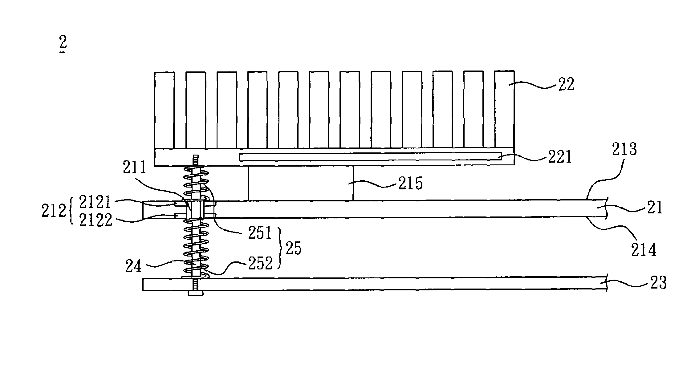
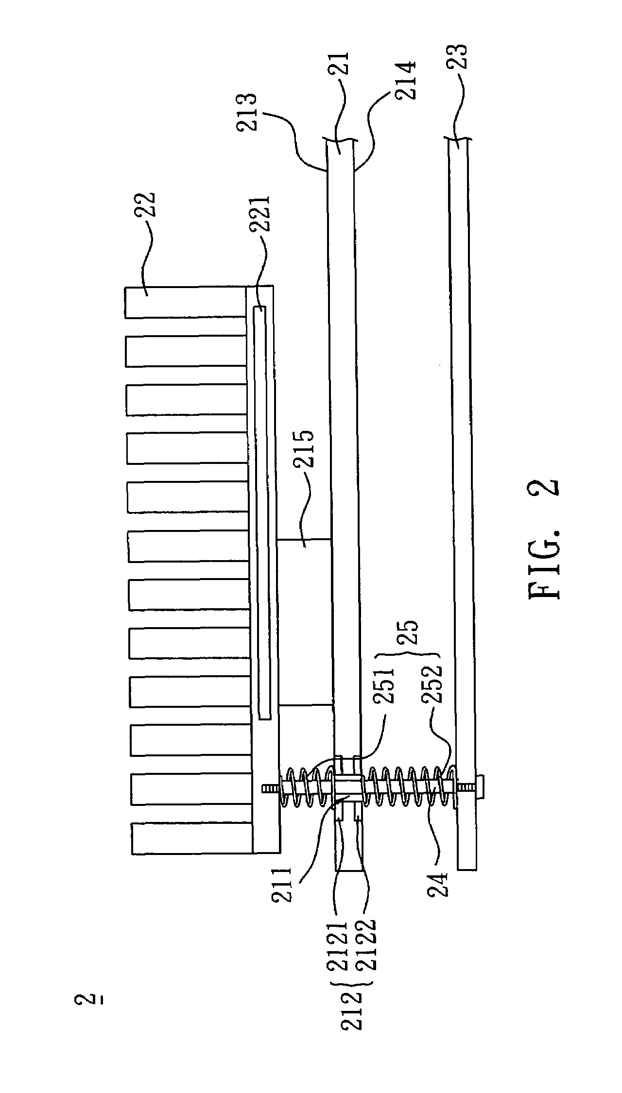
[0021]Referring to FIG. 2, an electronic system 2 according to a preferred embodiment of the invention includes a circuit board 21, a first conducting element 22, a second conducting element 23 and at least one connecting element 24. The type of the electronic system 2 is not fully restricted. For example, the electronic system 2 may be a fanless electronic system, or a system including at least one fan disposed on the first conducting element 22 or the second conducting element 23. In this embodiment, the fanless electronic system will be described as an example.

[0022]Referring again to FIG. 2, in the electronic system 2, the circuit board 21 has at least one through hole 211 and at least one grounding unit 212 disposed around the through hole 211. In this embodiment, the grounding u...


PUM


Abstract

An electronic system includes a circuit board, a first conducting element, a second conducting element and at least one connecting element. In this case, the circuit board has at least one through hole and at least one grounding unit disposed around the through hole. The first conducting element is disposed on one side of the circuit board, and the second conducting element is disposed on the other side of the circuit board. The connecting element is disposed through the through hole for connecting the first conducting element and the second conducting element.

Description

BACKGROUND OF THE INVENTION[0001]1. Field of Invention[0002]The invention relates to an electronic system, and, in particular, to an electronic system having the heat dissipating function.[0003]2. Related Art[0004]With the progress of the modern technology, various multimedia apparatuses, desktop computers and notebook computers are designed in more compact and having powerful functions. However, as the product performance is getting higher and higher, the number of the used electronic elements is increased. Accordingly, the heat dissipating requirement is getting higher and higher because the heat dissipating effect directly determines the lifetime of each electronic apparatus.[0005]The active heat dissipating system in the early age includes a combination of a fan and a heat sink. Such a combination, however, has low heat dissipation efficiency and high power consumption and occupies a larger space. Thus, the fanless heat dissipating system is gradually developed to replace the co...

Claims


Application Information

Patent Timeline
Patent Type & Authority Patents(United States)
IPC IPC(8): H05K7/20
CPCG06F1/182G06F1/20H01L23/4006H05K1/0215H01L2023/4056H01L2023/4062H01L2023/4081H01L2924/0002H05K3/4046H01L2924/00
Inventor KUO, ROBERTHSYU, JAMESCHANG, LANGHANSHUANG, STANLEY
Owner VIA TECH INC
Why Eureka
Try Eureka