Network data base control device and method thereof

a network data base and control device technology, applied in the field of network control devices and methods, can solve the problems of large amount of snmp packets flowing through, large burden on channels, and extremely heavy load on printers and network boards, and achieve the effect of reducing the load on device channels

Inactive Publication Date: 2008-10-28
CANON KK
View PDF39 Cites 38 Cited by
  • Summary
  • Abstract
  • Description
  • Claims
  • Application Information

AI Technical Summary

Benefits of technology

[0018]In view of the above circumstances, it is therefore an object of this invention to provide a network data base control device and method thereof which does not simultaneously acquire all MIB object information controlled by the network management software and therefore will have no simultaneous flow of a large volume of SNMP packets, and along with reducing the load on the device channels, the load on devices such as the printer which process the SNMP packets and load on the network board will be small.
[0019]A further object is to provide a network data base control device and method thereof wherein, by making the load on the LAN, printer and network boards small, the time required to start up (display initial menu) the network management software will be shortened and the user will thus be provided with an easier operating environment.
[0020]Still another object is to provide a network data base control device and method thereof wherein, in network printer management software utilizing the SNMP protocol, no processing change or write requests are made for unnecessary MIB data, while write requests for necessary MIB data for SNMP agents of the device (such as printers) on the network matching write-specified information from the user will be processed, thus allowing the amount of network traffic (data flow rate) and the load (amount of work) applied to the network printer to be reduced.
[0030]This invention also is capable of reducing the network traffic (data volume) and reducing the load (work load) applied to the network printer.

Problems solved by technology

However, on starting up the network management software, and acquiring all the MIB objects controlled by the network management software, a massive quantity of SNMP packets flow through the LAN at nearly the same time.
This flow places a large burden on the channels and at the same time also places an extremely heavy load on the printer and the network boards that process those SNMP packets.
Also, along with this increased load, the startup of the network management software also requires more time (initial menu display) which causes the user to feel stressed.
However writing all of the MIB data each time is not always necessary and the process is redundant.

Method used


Image

  • Network data base control device and method thereof
  • Network data base control device and method thereof
  • Network data base control device and method thereof

Examples


first embodiment

[0670]Next, a first embodiment for display that will not cause the user stress is explained from the device list window 801 to the device window 701.

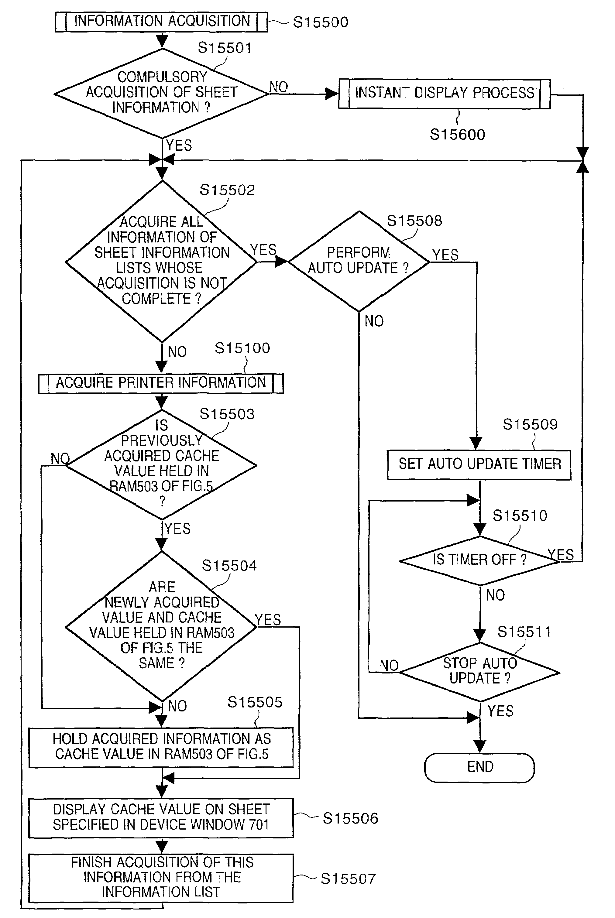
[0671]In FIG. 152, the flowchart shows the device window display operation for the network controller software (NetSpot) that the user is currently starting up.

[0672]The NetSpot program executed according to this flowchart is stored in a hard disk (HD) 511. A CPU501 is the main hardware element in running this NetSpot program. However, the main control element for the software is the NetSpot stored in the hard disk (HD) 511. In this embodiment, the operating system (OS) is assumed to be Windows95 however the OS is not limited to this.

[0673]A device window 701 shown in FIG. 7 opens when the user double-clicks the icon showing the device in Step S15201 in the NetSpot program. This device window 701 is shown on the CRT display of CRT 510 by ways of the CRT controller 506 by way of the PC500. However, at the completion of Step 15201, only t...

second embodiment

[0757]Hereafter a working example in the second embodiment is given for displaying the device list window 701 from the device window 801 to prevent the user from feeling stress due to delays in operation.

[0758]In FIG. 158, the process in the flowchart starts by the user operating the device window for the network management software (NetSpot) during the current start-up.

[0759]The NetSpot program executed according to this flowchart is stored in a hard disk (HD) 511. A CPU501 is the main hardware element in running this NetSpot program. However, the main control element for the software is the NetSpot stored in the hard disk (HD) 511. In this embodiment, the operating system (OS) is assumed to be Windows95 (Microsoft Corporation) however the OS is not limited to this.

[0760]When the user double-clicks the icons displaying the devices, the device window 701 shown in FIG. 7 is opened in Step S15801. In this step, operation is completely the same as in Step S15201 of the first embodiment...


PUM


Abstract

A network device control unit and method are provided in which, not all MIB objects under the control of the network management software are simultaneously acquired during startup of the network management software so the almost simultaneous flow of a large volume of SNMP packets in the LAN will not occur and along with a simultaneous reduction in the load on communications lines, the load on devices such as the printer and network board processing their SNMP packets will also become small. To accomplish this, windows allocated to individual network peripheral devices on a one to one basis and controlling the network device are utilized as device windows, and information to be displayed on the initial screen of the device window is acquired as the initial sheet and displayed. Device windows also acquire and display different sheet information on the device window when determined an entry has been made by the user requesting display of a different type of sheet information.

Description

BACKGROUND OF THE INVENTION[0001]This invention relates to a network control device and method including network control software.[0002]In recent years local area networks (LAN) for connecting computers together have become widespread. These type of local area networks are capable of connecting computers in the same floor of a building or the entire building, a group of buildings, a district or even larger areas and can even connect to networks on a worldwide scale. Each of these mutually connected local area networks (LAN) may utilize diverse hardware connection technology or a plurality of network protocol.[0003]Other isolated local area networks (LAN) of simple structure can be supervised by individual users. In other words, the user can replace equipment, install software and diagnose problems.[0004]However, large-scale complex LAN and large, mutually interconnected LAN groups require management referred to here as “Management”. This “Management” means both a person to act as th...

Claims


Application Information

Patent Timeline
Patent Type & Authority Patents(United States)
IPC IPC(8): G06F15/173G06F15/177H04L12/24H04L29/12
CPCH04L29/12009H04L41/0213H04L41/22H04L61/00
Inventor IGARASHI, TOSHIAKISUGIYAMA, AKIRAIIZUKA, YOSHIOTORII, MINORU
Owner CANON KK
Why Eureka
Try Eureka