Web tension profile measuring method and roll applying the same

a web tension profile and measurement method technology, applied in the direction of force/torque/work measurement apparatus, instruments, liquid/fluent solid measurement, etc., can solve the problems of only working sensors, direct-voltage component changes, long-duration compression, etc., to achieve sufficiently precise measurement of the web tension profile and improve the effect of measuring accuracy

Inactive Publication Date: 2008-11-04
VALMET TECH INC
View PDF9 Cites 21 Cited by
  • Summary
  • Abstract
  • Description
  • Claims
  • Application Information

AI Technical Summary

Benefits of technology

[0003]It is an object of the invention to enable measuring a web or the like, for example a drying felt, for its CD-profile (cross-directional profile) from a running machine by means of a simple measuring system. The use of helical film sensors planted on a roll surface is known for example from the patent FI 113804B. The purpose of this invention is to improve measuring accuracy as compared to the use of a spirally shaped sensor described in the cited patent and to enable a sufficiently precise measurement of the web tension profile in a manner that is simpler than using several adjacent sensors as set forth in the cited application and to attain a resolution which is better than what is accomplished by a spiral sensor described in the cited publication.
[0007]A solution according to a preferred embodiment of the invention has a further objective to provide a method of measuring a nip pressure indirectly by measuring a nip-influenced change in the tension profile. Another objective of the preferred embodiment is to provide an easy-to-retrofit and -replace sensor.
[0011]Surprisingly, a preferred measuring geometry in the measurement of web tension includes in fact a wide overlap angle and a pressure-sensitive film sensor almost equal in length to the overlap angle in pressure measuring service. In addition, because a pressure-sensitive film sensor keeps measuring an integral of its entire surface area, it is preferred to have a narrow sensor, with the result that a small width on the roll surface causes voltage variation between the leading and trailing edges and a lateral resolution is high. This is easy to carry out by way of an EMFi-film laid in a spiral configuration.

Problems solved by technology

The sensor operates as a dynamic sensor, which does not provide a constant result in long-duration compression, but the direct-voltage component applied across the sensor changes as a result of current losses.
Consequently, the sensor only works when it experiences pressure changes.
However, in the process of measuring web tension, it was discovered that this approach does not work, it being actually preferable to have as long a web overlap angle as possible and a sensor concealment not exceeding the overlap angle, whereby the sensor winds itself under the overlapping web until it is totally concealed thereby and after this the sensor emerges from under the overlap until it is once more totally clear of the concealment.

Method used


Image

  • Web tension profile measuring method and roll applying the same
  • Web tension profile measuring method and roll applying the same
  • Web tension profile measuring method and roll applying the same

Examples


Embodiment Construction

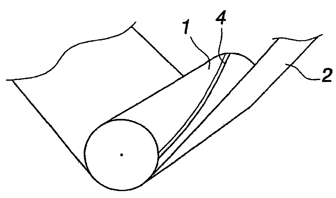
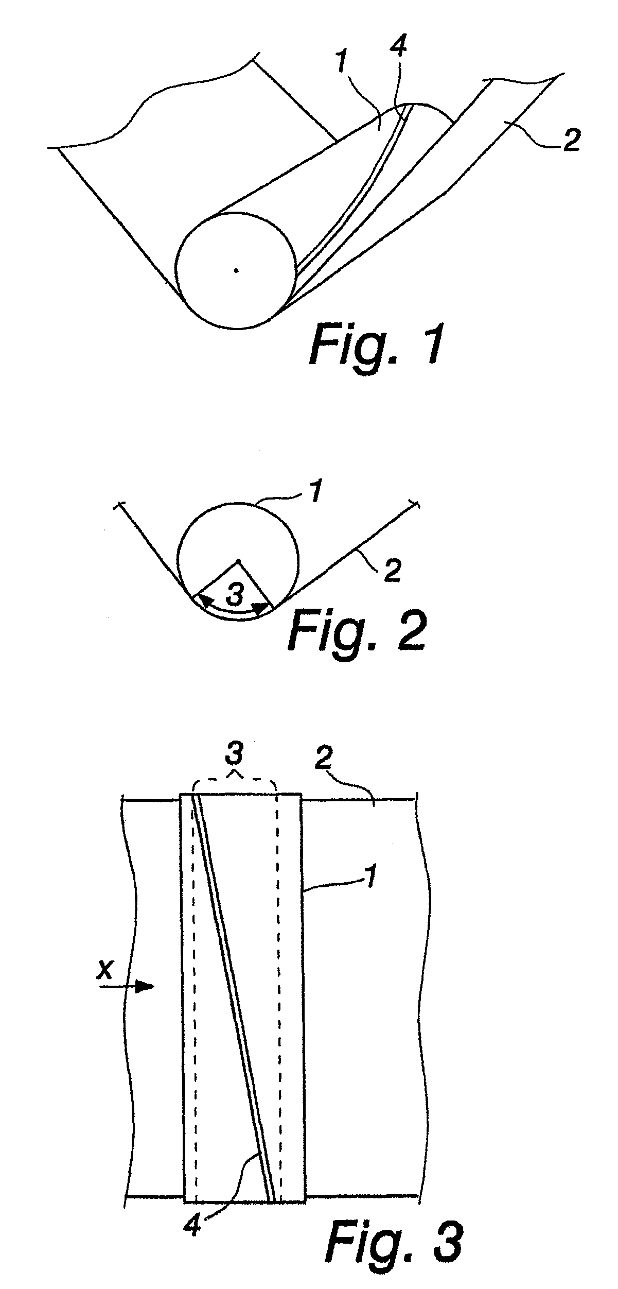
[0020]FIGS. 1-3 illustrate a sensor 4, which is planted on a roll 1 or preferably buried under a coating of the roll 1 and which is a segment of a spiral helix. The sensor has a helical pitch in the running direction of a web 2 which in the illustrated example is slightly less than an overlap angle 3. The overlap angle refers to a section of the roll, which is in contact with the web and over which section the web produces a tension-defined constant pressure on each segment of the roll. In FIG. 1, the sensor is depicted outside the overlap angle, in FIG. 3 the sensor is depicted completely within the overlap angle 3.

[0021]A protection groove can be prepared for the sensor 4 for planting the sensor therein. Thus, the sensor is preferably more or less flush with the surrounding surface. A pressure produced by the web 2 is transmitted to the sensor 4 by a possibly overlaid coating. The sensor itself is fixed for example by sizing or taping. The sensor must be planted on a smooth surfac...


PUM

PropertyMeasurementUnit
thicknessaaaaaaaaaa
widthaaaaaaaaaa
lateral tensionaaaaaaaaaa

Abstract

A method and a roll for measuring a tension profile is provided. The roll has planted on its surface a spirally helical pressure-sensitive film sensor, such as an EMFi pressure-sensitive film sensor, which makes contact with a web obliquely and which, co-directionally with the web, has a measuring range which is substantially equal to or shorter than a web overlap angle when the roll is used for measuring a lateral tension profile of the web.

Description

CROSS-REFERENCE TO RELATED APPLICATIONS[0001]This is a continuation of PCT / FI2006 / 050027, filed Jan. 17, 2006, which International Application was published by the International Bureau in English on Jul. 20, 2006, and also claims the benefit of Finnish Priority Application No. 20055019, filed Jan. 17, 2005, all of which are incorporated by reference herein in their entirety.BACKGROUND OF THE INVENTIONField of the Invention[0002]The application relates to measuring the tension profile of a stretching fibrous web running past a rotating roll, such as a stretching paper, board, tissue or the like fibrous material, such as the dewatering or drying fabric of a paper machine. The invention is also applied in the context of a stretching fibrous web in paper, board or tissue making machines or in further processing machines for papers, such as guillotines or printing presses.BRIEF SUMMARY OF THE INVENTION[0003]It is an object of the invention to enable measuring a web or the like, for examp...

Claims


Application Information

Patent Timeline
Patent Type & Authority Patents(United States)
IPC IPC(8): G01L5/04B65H23/02D21FD21F1/40D21G9/00G01L5/108
CPCB65H23/0204D21F1/40D21G9/0009G01L5/045G01L5/10B65H2515/314B65H2553/00B65H2553/81B65H2553/822B65H2553/82
Inventor INNALA, MATTIKINNUNEN, JORMAKOSKELAINEN, JUSSIPITKANEN, TATULANNES, PETTERINYLUND, MARKUSTIILIKAINEN, MARKOSALONIEMI, JYRKIHUUSKONEN, REIJO
Owner VALMET TECH INC
Why Eureka
Try Eureka