Electrically-driven steering column apparatus

a technology of electric motors and steering columns, which is applied in mechanical devices, couplings, transportation and packaging, etc., can solve the problems of large scale, complex and complicated configuration of the whole apparatus, and the frequency of vibration and noise, so as to reduce the number of components, the effect of high rigidity and smooth operation

Inactive Publication Date: 2008-11-04
NSK LTD
View PDF24 Cites 18 Cited by
  • Summary
  • Abstract
  • Description
  • Claims
  • Application Information

AI Technical Summary

Benefits of technology

[0008]It is an object of the present invention, which was devised under the circumstances described above, to provide an electrically-driven steering column apparatus actualizing a compact configuration, a high rigidity and a reduction in the number of components while scheming to attain a smooth operation.
[0016]Thus, in the case of adopting the synthetic resin member, an elasticity of the synthetic resin member makes it difficult to cause a backlash between the spherical joint element and the cylindrical joint element, and, in addition, it is possible to restrain an emission of noises and an occurrence of abrasion due to a metal-to-metal contact.

Problems solved by technology

In the electrically-driven tilt type steering column apparatus described above, the link mechanism, etc. explained above becomes large in scale in terms of swinging the swing-side column having a comparatively heavy weight about the tilt pivot as a fulcrum, and therefore the configuration of the whole apparatus has no alternative but to become complicated and large in scale.
On the other hand, the electrically-driven telescopic type steering column apparatus has a variety of problems derived from the power transmission means.
For instance, in the Japanese Utility Model Laid-Open Publication No. 63-165269, a telescopic motion of an inner column through the screw shaft and a support bracket involves elongating a transmission route for the driving force given from the electric motor, with the result that vibrations and noises are rarely caused because of the screw shaft and the support bracket being flexed.
Especially, the screw shaft is not allowed to increase much of a diameter for the reasons of saving a space, a weight and a cost, and hence its strength inevitably decreases.
Further, the apparatus disclosed in Japanese Patent Application Laid-Open Publication No. 13-18809 given above has less of such inconveniences, however, on the occasion of engaging the feed screw mechanism as a driving rod with the bracket, if not precisely attached so that the driving rod becomes parallel with the telescopic direction of the inner column, it happens that those components do not move smoothly as an excessive force acts thereon when in the telescopic operation.

Method used


Image

  • Electrically-driven steering column apparatus
  • Electrically-driven steering column apparatus
  • Electrically-driven steering column apparatus

Examples


first embodiment

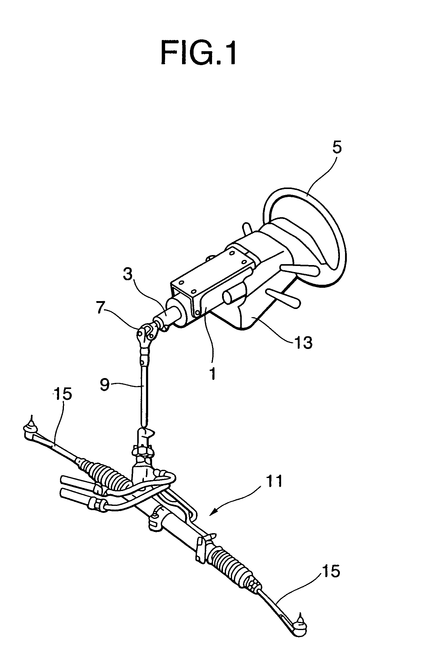
[0051]FIG. 1 is a perspective view showing car-room-side components of a hydraulic power steering apparatus in accordance with a A member designated by the numeral 1 in FIG. 1 is a steering column that rotatably supports an upper steering shaft 3. A steering wheel 5 is attached to an upper end of the upper steering shaft 3, and a lower steering shaft 9 is connected via a universal joint 7 to a lower end thereof.

[0052]A steering gear 11 constructed of a rack & pinion mechanism, a hydraulic power assist mechanism, etc. is further connected to a lower end of the lower steering shaft 9. Referring again to FIG. 1, the numeral 13 represents a column cover for covering the steering column 1, and the numeral 15 denotes a tie rod connected to right and left ends of the steering gear 11.

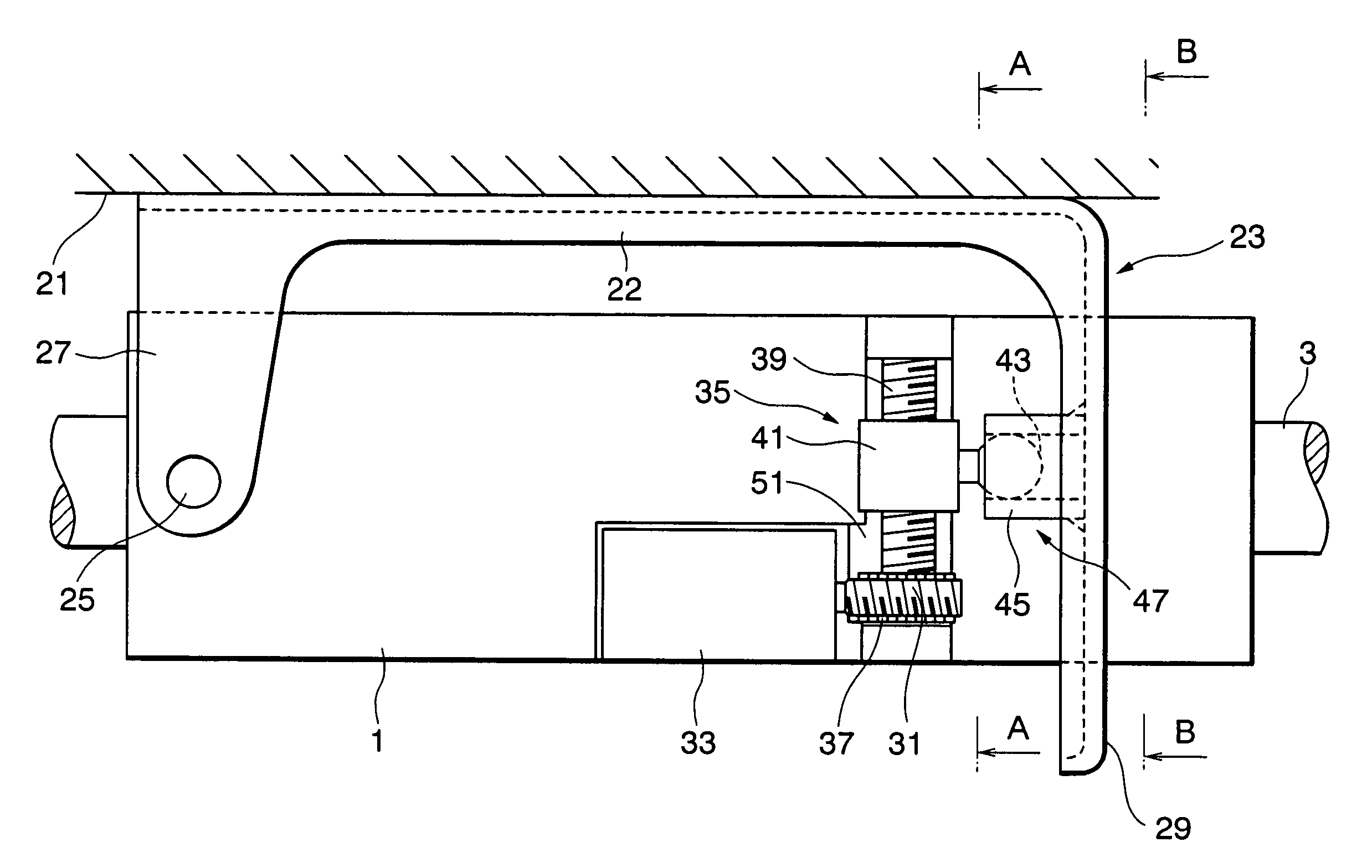
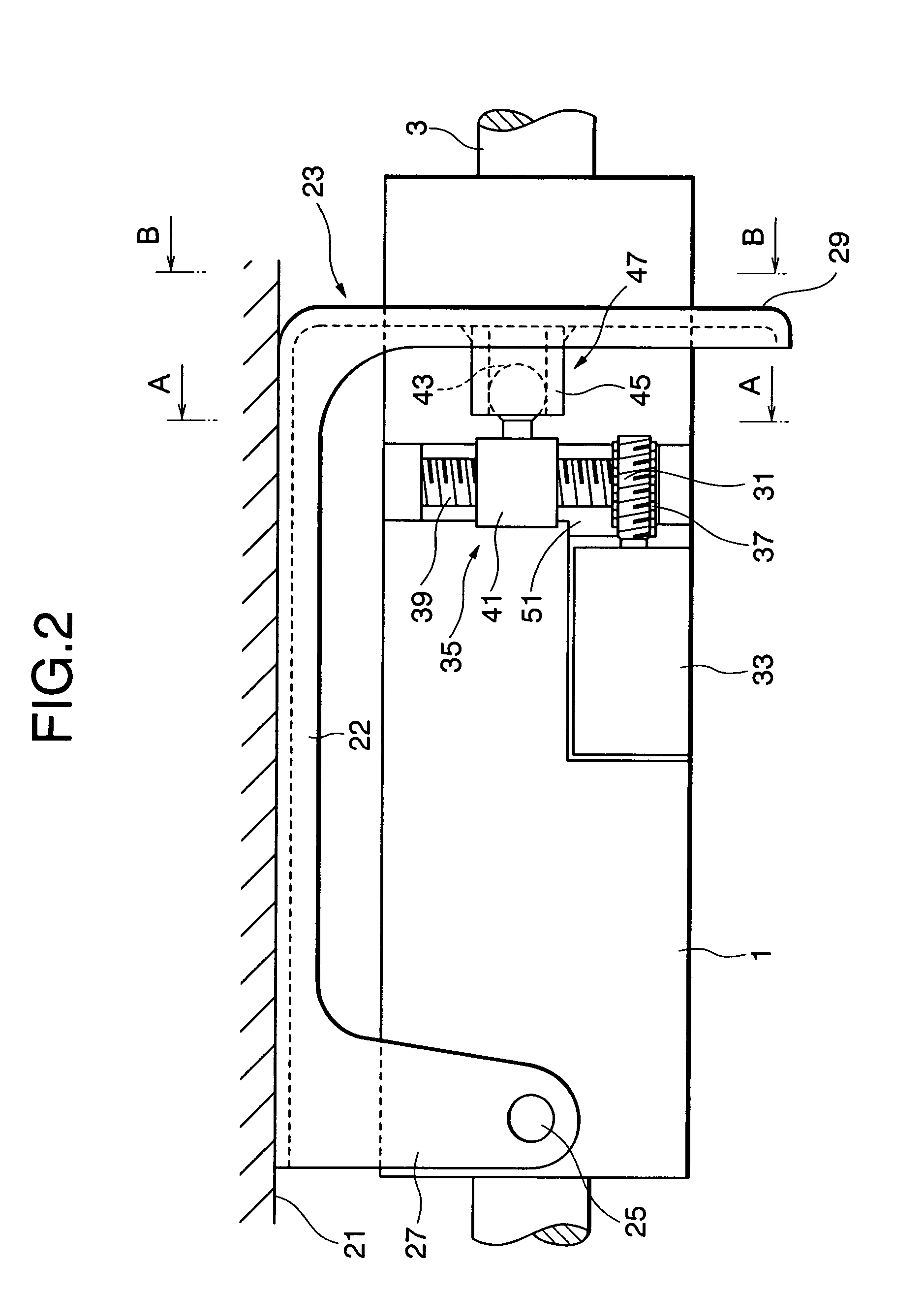
[0053]FIG. 2 is a schematic view showing a configuration of the electrically-driven tilt type steering column apparatus in the first embodiment of the present invention. FIG. 3 is a sectional view taken along...

second embodiment

[0066]Therefore, the sleeve 45 is provided on the side of the inner column 63, and the ball stud 43 slidably fitted in the interior of the sleeve 45 is provided on the side of the outer column 61. Thus, it may be sufficient to simply fit the ball stud 43 into the sleeve 45 as illustrated in FIG. 10. With this contrivance, even if an axis deviation occurs to some extent between the feed screw shaft 39 and the steering shaft 3, the joint 47 composed of the ball stud 43 and the sleeve 45 relatively slides, thereby absorbing this axis deviation.

[0067]If there occurs a deviation in parallelism of the feed screw shaft 39 with respect to the steering shaft 3, a ball unit 43 autonomously rotates and slides within the sleeve 45 when in the telescopic operation, thereby absorbing this deviation and also a deviation in parallelism that might occur when assembling the components. Further, if there occurs a deviation in axis-to-axis distance between the feed screw shaft 39 and the steering shaf...


PUM


Abstract

An electrically-driven steering column apparatus includes a steering column rotatably holding a steering shaft and capable of adjusting a position of the steering wheel, and a power transmission mechanism for transmitting to the steering column a rotational driving force of an electric motor as a position adjusting motion driving force, wherein the power transmission mechanism has a joint constructed of a spherical joint element and a cylindrical joint element in which the spherical joint element is slidably fitted, on within a driving force transmission route.

Description

CROSS-REFERENCE TO RELATED APPLICATION[0001]This application is a division of application Ser. No. 10 / 484,499 filed Jan. 22, 2004 now abandoned, which is a 371 of PCT / JP03 / 03094 filed Mar. 14, 2003.TECHNICAL FIELD[0002]The present invention relates generally to an electrically-driven steering column apparatus, and more particularly to a technology scheming to configure the apparatus in a compact size and to reduce a manufacturing costs thereof, and so on.BACKGROUND ART[0003]A steering apparatus of an automobile is used (steered) by a multiplicity of unspecified drivers, and it is therefore desired that a position of a steering wheel be easily adjusted corresponding to an individual physique, a driving posture, etc. There increases the number of apparatuses adopting an electrically-driven tilt mechanism and an electrically-driven telescopic mechanism in order to meet such a demand.[0004]The electrically-driven tilt type steering column apparatus is an apparatus for adjusting the posi...

Claims


Application Information

Patent Timeline
Patent Type & Authority Patents(United States)
IPC IPC(8): B62D1/16B62D1/18B62D1/181B62D1/185F16C11/06
CPCB62D1/181B62D1/185F16C11/0657Y10T74/2003Y10T403/455F16C2326/24
Inventor TOMARU, MASAKIMITSUHASHI, CHIEFUJIWARA, TAKESHISHIBUYA, YASUHIRO
Owner NSK LTD
Why Eureka
Try Eureka