Opposed pumping load high pressure common rail fuel pump

a fuel pump and high-pressure technology, applied in the direction of pump parameters, piston pumps, positive-displacement liquid engines, etc., can solve the problems of no alternative, design, development, testing, etc., and the development cost of per engine is relatively high, and the cost of a new pump is considerabl

Inactive Publication Date: 2008-11-04
CATERPILLAR INC
View PDF31 Cites 10 Cited by
  • Summary
  • Abstract
  • Description
  • Claims
  • Application Information

AI Technical Summary

Problems solved by technology

Those skilled in the art will appreciate that designing, developing, testing, etc. a new pump can involve considerable expense.
While this expense may be distributed over the expected number of engines, when volumes are relatively low, the per engine development cost can be relatively high.
Unfortunately, there has often been no alternative since an off-the-shelf alternative is typically unable to meet, or be easily modified to meet, all of the specific requirements of the new fuel system application.
These torque reversals can produce unwanted stress in the gear train and cam shaft, as well as produce undesirable noise emissions.
These repeated loads over the life of the pump can cause significant wear on bearings supporting the cam shaft.
Because common rail fuel pumps often raise fuel pressure to extremely high levels, and are expected to undergo many millions of pumping strokes in their useful life, bearings can prematurely wear and the cam shaft can suffer from cyclic fatigue loading.
These factors can cause the pump to be overdesigned to compensate for these cyclic stresses, or can result in premature failure of a pump if these stress issues are not adequately taken into account.
In either case, costs are undesirably increased.

Method used


Image

  • Opposed pumping load high pressure common rail fuel pump
  • Opposed pumping load high pressure common rail fuel pump
  • Opposed pumping load high pressure common rail fuel pump

Examples


Embodiment Construction

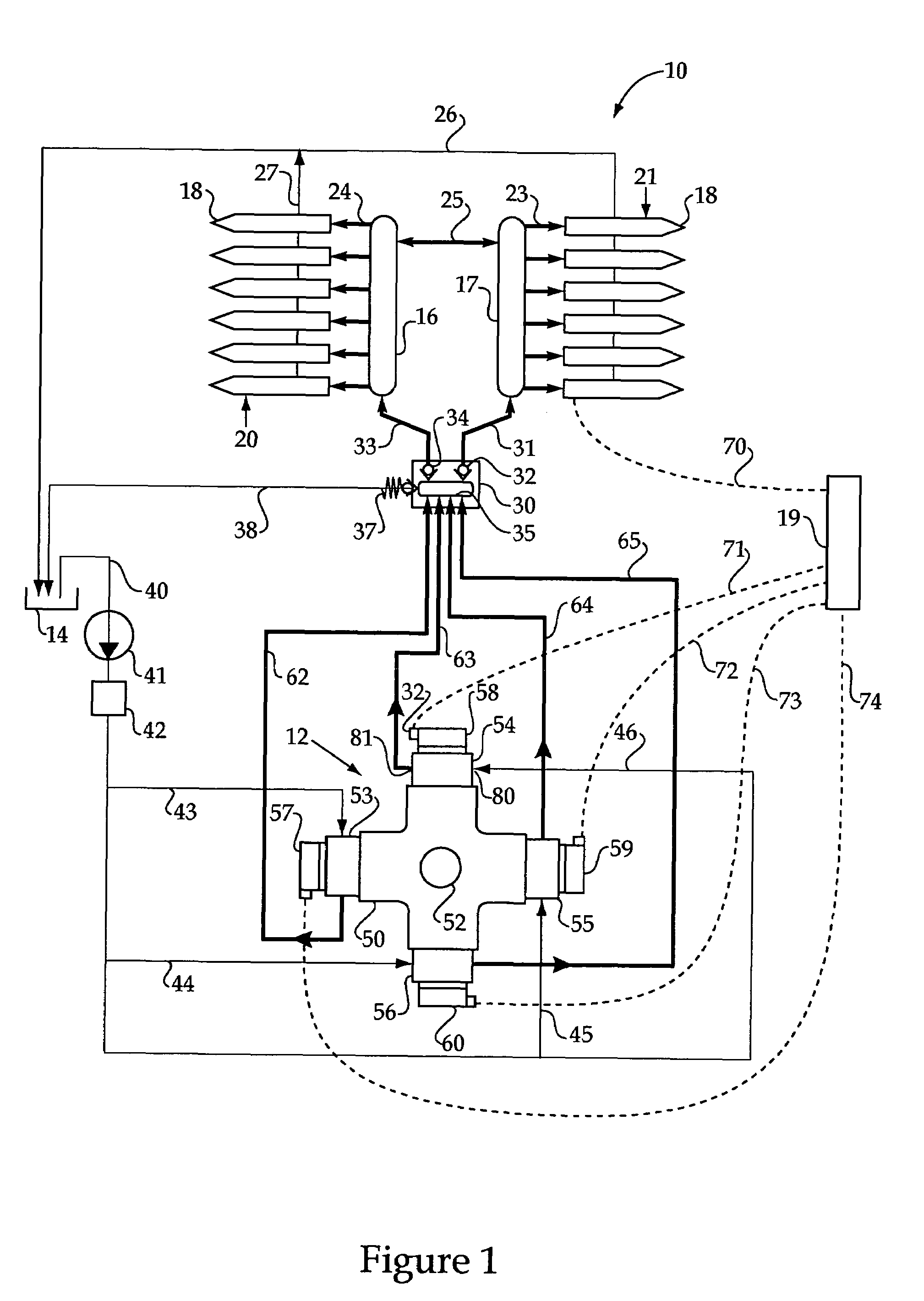
[0013]Referring to FIG. 1, a common rail fuel system 10 includes a high pressure fuel pump 12, a low pressure fuel supply reservoir 14, common rails 16 and 17, and a plurality of fuel injectors 18. In the illustrated embodiment, fuel injectors 18 are distributed in a left bank 20 and a right bank 21 that utilize respective common rails 16 and 17, which are in fluid communication with one another in a known manner via pressure communication passage 25. Thus, fuel system 10 is configured for a V-type engine having 12 cylinders that each include a fuel injector 18 positioned for direct injection of fuel into the individual cylinders. Nevertheless, those skilled in the art will appreciate that the present disclosure is applicable to any engine configuration with any number of cylinders. However, the present disclosure is particularly applicable to large engines with many cylinders and a large fuel consumption demand.

[0014]Each of the individual fuel injectors 18 is electronically contro...


PUM


Abstract

A high volume high pressure common rail pump for a fuel system includes pairs of pump head assemblies in phase with each other but oriented in opposition to one another about a rotating cam shaft. Pump pistons in the pump head assemblies simultaneously undergo pumping strokes via a shared two lobe cam of the rotating cam shaft. The pump may include two pairs of pump head assemblies, and each head assembly may include two pump pistons. The cam shaft includes two cams sufficiently out of phase with one another that the cam shaft always has a positive torque even when the cam lobes are symmetrical. In addition, because the pumping is done simultaneously on opposite sides of the cam shaft, the forces on the cam shaft are balanced and its support bearings experience less wear and tear.

Description

TECHNICAL FIELD[0001]The present disclosure relates generally to high pressure pumps for fuel systems, and more particularly to pumps with pairs of pump assemblies oriented in opposition to one another for simultaneous pumping.BACKGROUND[0002]High pressure common rail fuel pumps for different engines have a variety of different characteristics suitable for their specific applications. Often times development of a new engine and associated fuel system can require a new pump design. Those skilled in the art will appreciate that designing, developing, testing, etc. a new pump can involve considerable expense. While this expense may be distributed over the expected number of engines, when volumes are relatively low, the per engine development cost can be relatively high. Unfortunately, there has often been no alternative since an off-the-shelf alternative is typically unable to meet, or be easily modified to meet, all of the specific requirements of the new fuel system application.[0003...

Claims


Application Information

Patent Timeline
Patent Type & Authority Patents(United States)
IPC IPC(8): F02M57/02F02M37/04F04B1/04
CPCF02M59/06F02M59/366F04B1/02F04B1/0413F04B9/042F04B49/24F04B1/0538F02M63/0295F02M2200/03F04B2201/1202F04B2201/1207
Inventor SHAFER, SCOTT F.TRUBNIKOV, TIMURLOVE V, WILLIAM JOHNREBHOLZ, HEATHERZHANG, JIANHUA
Owner CATERPILLAR INC
Why Eureka
Try Eureka