Drive motor mounting structure

a technology for mounting structures and drives, which is applied in the direction of jet propulsion mounting, positive displacement liquid engine, piston pump, etc., can solve the problems of a large number of additional steps, difficult to sufficiently attenuate the vibration transmitted by the drive motor to the vehicle body, and need a commensurate number of additional steps to complicate the removal of the drive motor. , to achieve the effect of enhancing workability and great attenuation of vibrations

Active Publication Date: 2008-11-04
NISSAN MOTOR CO LTD
View PDF13 Cites 25 Cited by
  • Summary
  • Abstract
  • Description
  • Claims
  • Application Information

AI Technical Summary

Benefits of technology

[0008]The present invention is made with such points in view. It therefore is an object of the invention to provide a drive motor mounting structure for vehicles allowing a great attenuation of vibrations being transmitted from a drive motor to a vehicle body, and an enhanced workability in removal of the drive motor.

Problems solved by technology

However, in the above-noted mounting structure, the component mounting frame having the drive motor mounted thereon is fixed via brackets to the upsides of the side members, where the areas are too narrow to allow a sufficient provision of anti-vibratory structure, so that it may be difficult to sufficiently attenuate vibrations being transmitted from the drive motor to the vehicle body.
Further, this mounting structure requires the central member to be mounted to the drive motor, this motor to be mounted to the component mounting frame, and this frame to be mounted to the side members, thus needing a commensurate number of additional steps of complicate work in removal of the drive motor.

Method used


Image

  • Drive motor mounting structure
  • Drive motor mounting structure
  • Drive motor mounting structure

Examples


Embodiment Construction

[0015]There will be detailed below a preferred embodiment of the present invention with reference to the accompanying drawings.

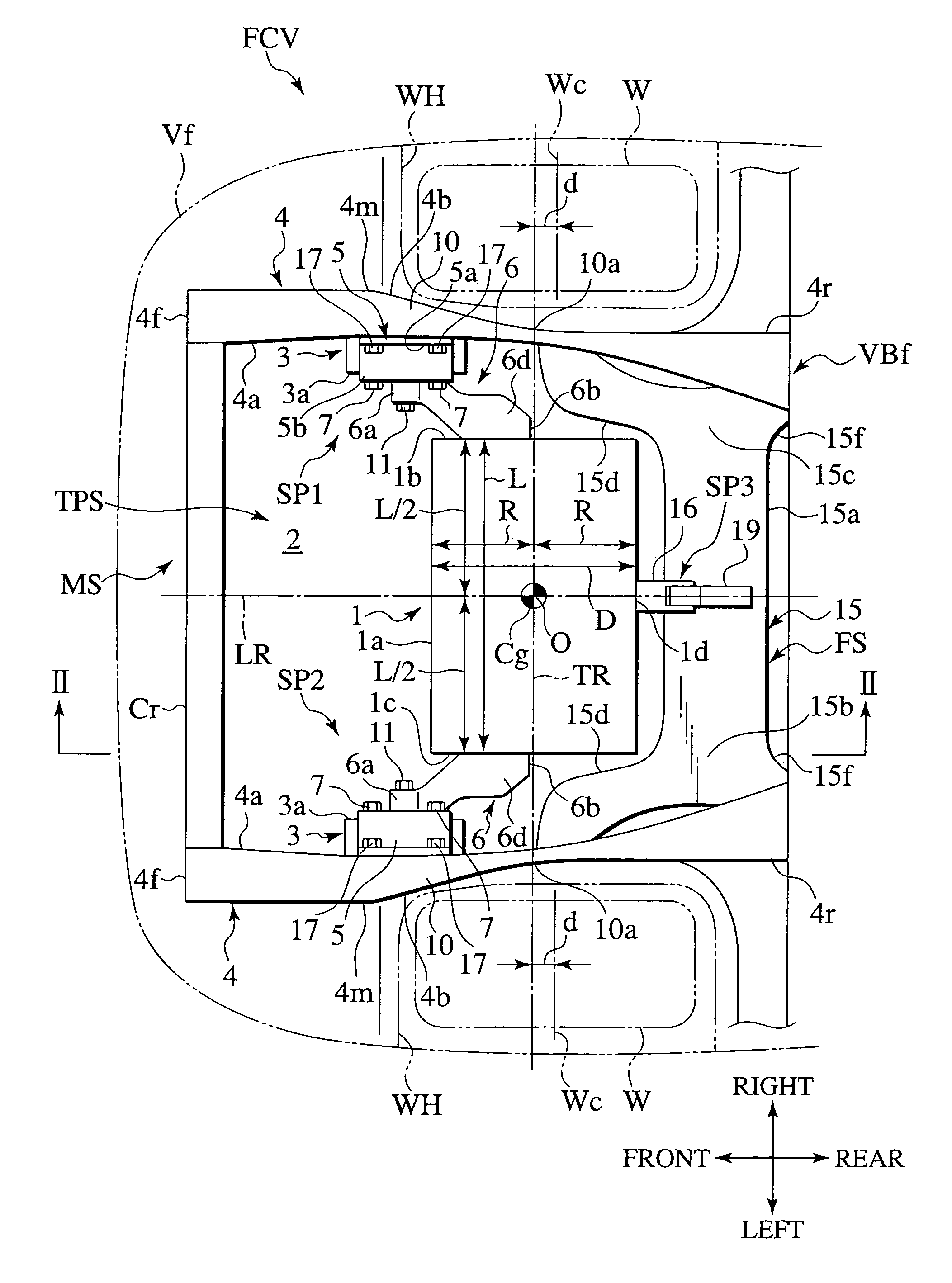
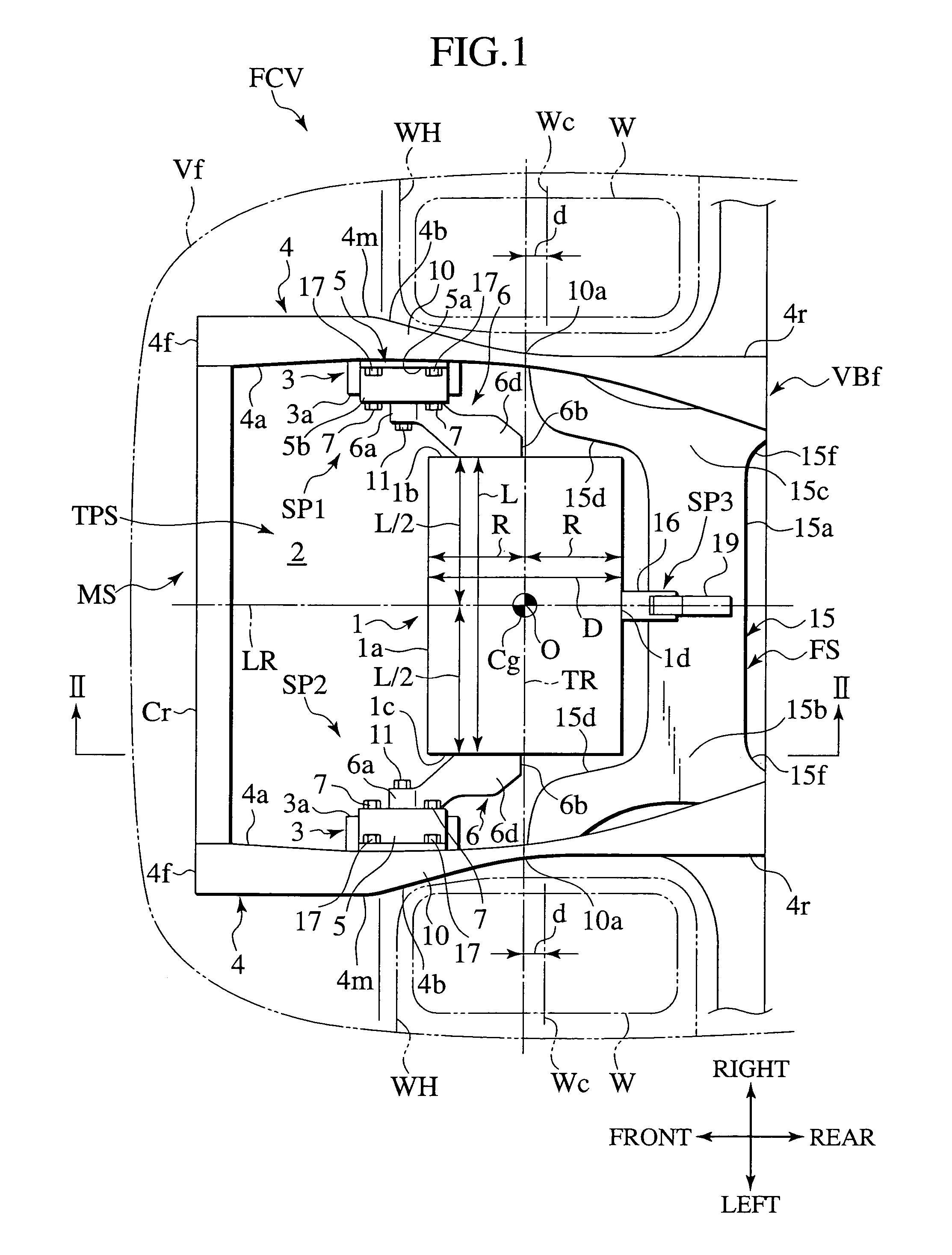
[0016]FIG. 1 shows, in plan, a front part Vf of a fuel cell vehicle FCV including a drive motor mounting structure MS according to an embodiment of the invention, FIG. 2 is a section II-II of FIG. 1, and FIG. 3 is a section III-III of FIG. 2.

[0017]The fuel cell vehicle FCV has a vehicle body of which a front portion VBf (FIGS. 1-2) includes a pair of vehicle-longitudinally extending rectangular-C-channel-shaped left and right side members 4, 4 (FIGS. 1-3).

[0018]The side members 4, 4 are interconnected at their front ends 4f (FIGS. 1-2) by a rectangular-C-channel-shaped cross member Cr (FIGS. 1-2), and at their downwardly slanting rearward extensions 4r (FIGS. 1-2) by a vehicle-transversely extending frame structure FS (FIG. 1-2) including a wheel-suspension-supporting sub-frame 15.

[0019]The sub-frame 15 is formed with a straight central portion 15a (FIGS. 1-...


PUM


Abstract

For spatial arrangement of a drive motor (1) in a motor room (2), a three-point support system (TPS) includes supports (SP1, SP2) having a vibration suppressing member (3) for suppressing vibrations to be transmitted from the drive motor (1), a first bracket (5) for fixing the vibration suppressing member (3) to a transversely inner lateral side (4a) of a side member (4) of a front part (VBf) of a vehicle body, and a second bracket (6) for fixing the drive motor (1) to the vibration suppressing member (3), while the first bracket (5) is fastened to the inner lateral side (4a) of the side member (4), and the second bracket (6) is fastened at a proximal end (6a) to the vibration suppressing member (3) and at a distal end (6b) to the drive motor (1) to be disposed lower than the side member (4), with a reduced vibration transmission from the drive motor (1) to the vehicle body, allowing a facilitated removal of the drive motor (1).

Description

BACKGROUND OF THE INVENTION[0001]1. Field of the Invention[0002]The present invention relates to a drive motor mounting structure, and particularly, to a drive motor mounting structure for vehicles to be driven with a drive motor and provided with a motor room for the drive motor to be mounted therein.[0003]2. Relevant Art[0004]Japanese Patent Application Laid-Open Publication No. 8-310252 has disclosed a mounting structure for mounting a drive motor to a vehicle body in an electric vehicle, in which a motor unit as a drive motor and a control unit therefor, as well as motor auxiliary equipment, are mounted on a single frame for mounting components, to provide a unit assembly, which is installed in a motor room, from thereunder, and mounted in position by using frame-end brackets provided on the component mounting frame and fixed by bolts and nuts to undersides of side members of the vehicle body, body-end brackets provided on upsides of the side members and fixed by bolts and nuts ...

Claims


Application Information

Patent Timeline
Patent Type & Authority Patents(United States)
IPC IPC(8): B60K1/00B60K3/00B60K5/12F04B17/00F04B35/00
CPCB60K5/1216
Inventor SHIGEMATSU, SATOSHI
Owner NISSAN MOTOR CO LTD
Why Eureka
Try Eureka