Automotive muffler

a technology of muffler and muffler body, which is applied in the direction of machines/engines, sound absorption, gas passages, etc., can solve the problems of high return pressure of circuitous muffler, harsh noise produced by exhaust ejected from internal combustion engines and directly injected into the atmosphere,

Inactive Publication Date: 2008-11-04
WU CHING LIN
View PDF27 Cites 10 Cited by
  • Summary
  • Abstract
  • Description
  • Claims
  • Application Information

AI Technical Summary

Benefits of technology

[0010]It is a primary object of the invention to eliminate the above-mentioned drawbacks and to provide an automotive muffler that ensures the decrease of the return pressure according to the increase of the exhaust velocity.
[0011]It is another object of the invention to provide an automotive muffler that achieves the circuitous sound-deadening effect and guarantees the least resistance of the exhaust gas flow for obtaining an optimal engine efficiency. Meanwhile, the output horsepower can be raised at more than 20%.
[0012]The principle employed in the invention lies in that the exhaust gas flow field can be expanded to different sound-absorbing chambers when the gas ejected from the engine is injected into a muffler. Meanwhile, the sound-absorbing chamber consists of several tubes interconnected in the axial direction. All of the tubes have a widened inlet section and a narrow outlet section to fulfill the requirements of Venturi tube and to create the Venturi tube effect. According to Bernoulli's equation,Q=φ1×V1=φ2×V2the change of the flow velocity can be determined.
[0013]Under the condition that the exhaust at the same flow rate Q passes through the front and rear through holes, the velocity V2 increases due to decrease of the diameter of the through hole φ2. In this way, an enhanced flow velocity within the sound-deadening tube can be achieved. Meanwhile, such a flow velocity results in a suction effect around the jet flow nozzle. Therefore, the exhaust gas flow field within the external tube can be moved. In other words, the exhaust may be rapidly ejected to create a “conduction action” after the exhaust within the tubes is expanded and sound-deadened. Accordingly, the pumping loss of the engine may be minimized for enhancing the horsepower without increase of the noise.

Problems solved by technology

The exhaust ejected from the internal combustion engine and directly injected into the atmosphere will produce a harsh noise since the gas pressure of the exhaust is suddenly reduced from a high level to an atmospheric level.
The circuitous muffler has the problem of great return pressure due to the complicated flowing path of exhaust.
However, the straight-way type muffler 20 has difficulties in absorbing the exhaust sound, thereby causing noise problem.
In other words, one part of the exhaust remains within the cylinder and is mixed with fresh oil vapor, thereby affecting the performance of engine.
This is one of the sources of the pumping loss.
They can not fulfill the requirements of low noise and maximal horsepower.

Method used


Image

  • Automotive muffler
  • Automotive muffler
  • Automotive muffler

Examples


Embodiment Construction

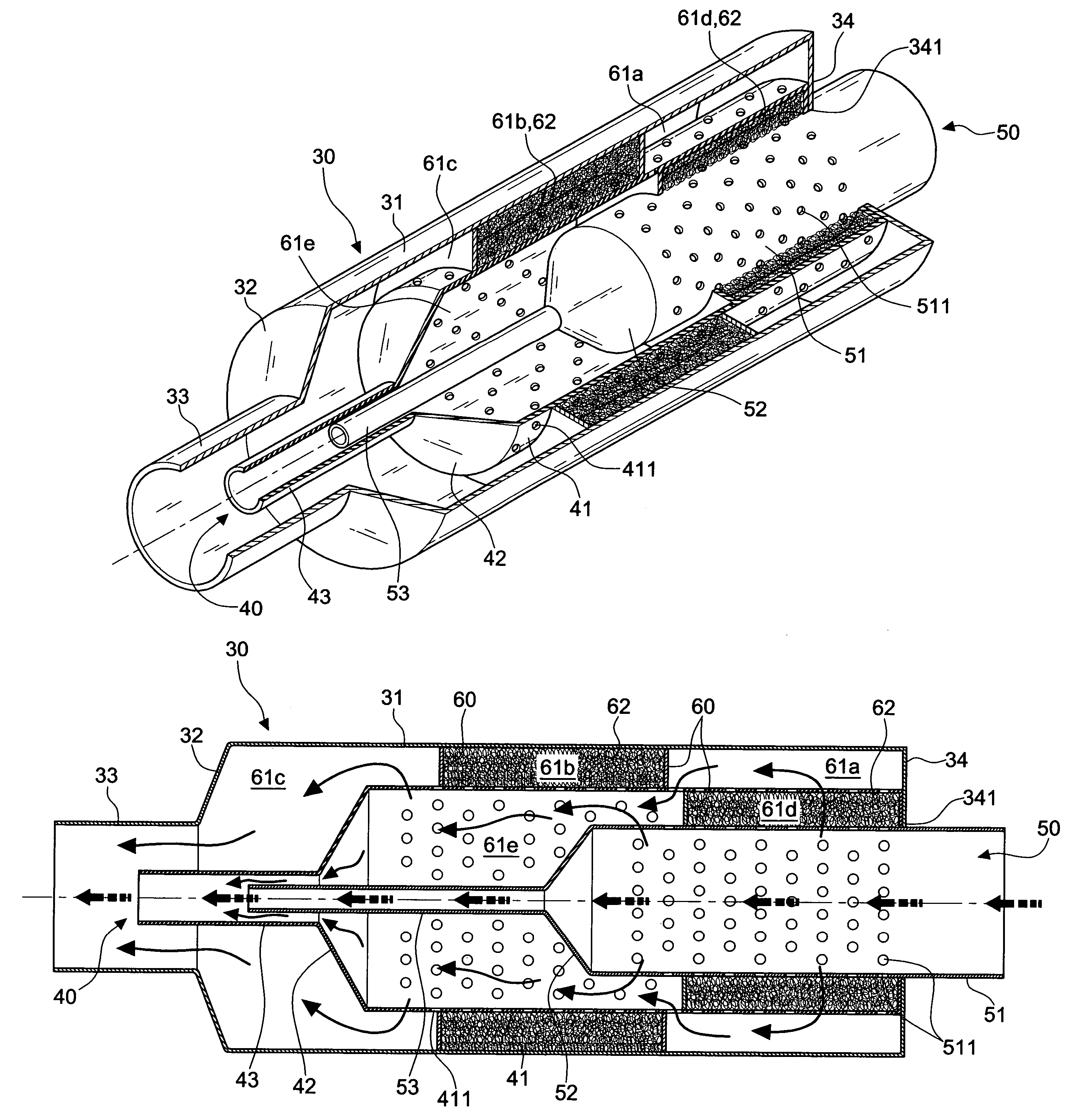
[0025]Referring to FIGS. 3 and 4, an automotive muffler in accordance with a preferred embodiment of the invention includes an external tube 30, an internal tube 40, an internal guide tube 50, and a plurality of partitions 60.

[0026]The external tube 30 consists of a first widened section 31, a first tapering section 32, and a first narrow section 33. The first widened section 31 includes a sealing wall 34 with a through hole 341 at the front end thereof.

[0027]The internal tube 40 consists of a second widened section 41, a second tapering section 42, and a second narrow section 43. The internal tube 40 is disposed within the external tube 30 in such a manner that the front end of the second widened section 41 is compressed against the sealing wall 34 and the rear end of the second narrow section 43 is extended into the first narrow section 33. Besides, a plurality of vent holes 411 are formed in the wall of the second widened section 41.

[0028]The internal guide tube 50 consists of a ...


PUM


Abstract

An automotive muffler includes an external tube consisting of a first widened portion, a first tapering portion, and a first narrow portion, the first widened section having a sealing wall with a through hole at the front end thereof; an internal tube consisting of a second widened portion, a second tapering portion, and a second narrow portion, the internal tube being disposed within the external tube, a plurality of vent holes being formed in the wall of the second widened portion; an internal guide tube consisting of a third widened portion, a third tapering portion, and a third narrow portion, the internal guide tube being disposed within the internal tube, a plurality of vent holes being formed in the wall of the third widened section that is disposed within the internal pipe; and a plurality of partitions interposed between the first widened section and the second widened section as well as between the second widened section and the third widened section. In this way, a reduced pumping loss and an increase output horsepower of the engine may be achieved.

Description

BACKGROUND OF THE INVENTION[0001]1. Field of the Invention[0002]The present invention relates to an automotive muffler, and more particularly to an automotive muffler operating both in a circuitous and in a straight way. Meanwhile, the output horsepower can be enhanced.[0003]2. Description of the Related Art[0004]The exhaust ejected from the internal combustion engine and directly injected into the atmosphere will produce a harsh noise since the gas pressure of the exhaust is suddenly reduced from a high level to an atmospheric level. Thus, the exhaust has to pass through a sound-deadening unit for reducing the pressure and the frequency of the exhaust, thereby efficiently lowering the exhaust noise.[0005]A conventional automotive muffler 10, as shown in FIG. 1, operates in a circuitous way. The circuitous muffler includes partitions 12 within a cylindrical body 11 for separating a plurality of gas chambers 13. A plurality of the air guide tubes 14 are interconnected to one another ...

Claims


Application Information

Patent Timeline
Patent Type & Authority Patents(United States)
IPC IPC(8): F01N1/08F01N1/10F01N1/00F01N1/02F01N1/24
CPCF01N1/003F01N1/04F01N1/084F01N1/085F01N1/089F01N1/24F01N2310/00F01N2470/02F01N2590/04
Inventor WU, CHING-LIN
Owner WU CHING LIN
Why Eureka
Try Eureka