Bidirectional line switched ring network

a technology of switching ring and switching ring, which is applied in the field of bidirectional line switching ring network, can solve the problems of large amount of man-hours for software development and evaluation, unnecessary service interruption to network users, and large amount of man-hours for network users to be produced, so as to prevent a misconnection in the even

Inactive Publication Date: 2008-11-04
FUJITSU LTD
View PDF17 Cites 5 Cited by
  • Summary
  • Abstract
  • Description
  • Claims
  • Application Information

AI Technical Summary

Benefits of technology

[0026]Accordingly, it is an object of the present invention to provide a bidirectional line switched ring (BLSR) network which can prevent a misconnection in the event of multiple failures without providing a squelch table, and enables the squelch processing even under an arbitrary VT-channel setting condition.

Problems solved by technology

In this case, in order to squelch the VT-level channel, if this squelch is performed using an STS squelch table on an STS-level bases after bundling the VT-level channels to the STS, unnecessary service interruption to the network users may be produced.
As a result, unnecessary service interruption is produced against the network user.
Therefore, when implementing the aforementioned proposal, it is required to expand hardware memory capacity and software processing capacity, as well as a vast amount of man-hours for software development and evaluation.
In addition, when performing the squelch processing by software, increased loads produced by the concentrated processing in one node may undesirably cause a problem on the overall network performance.

Method used


Image

  • Bidirectional line switched ring network
  • Bidirectional line switched ring network
  • Bidirectional line switched ring network

Examples


Embodiment Construction

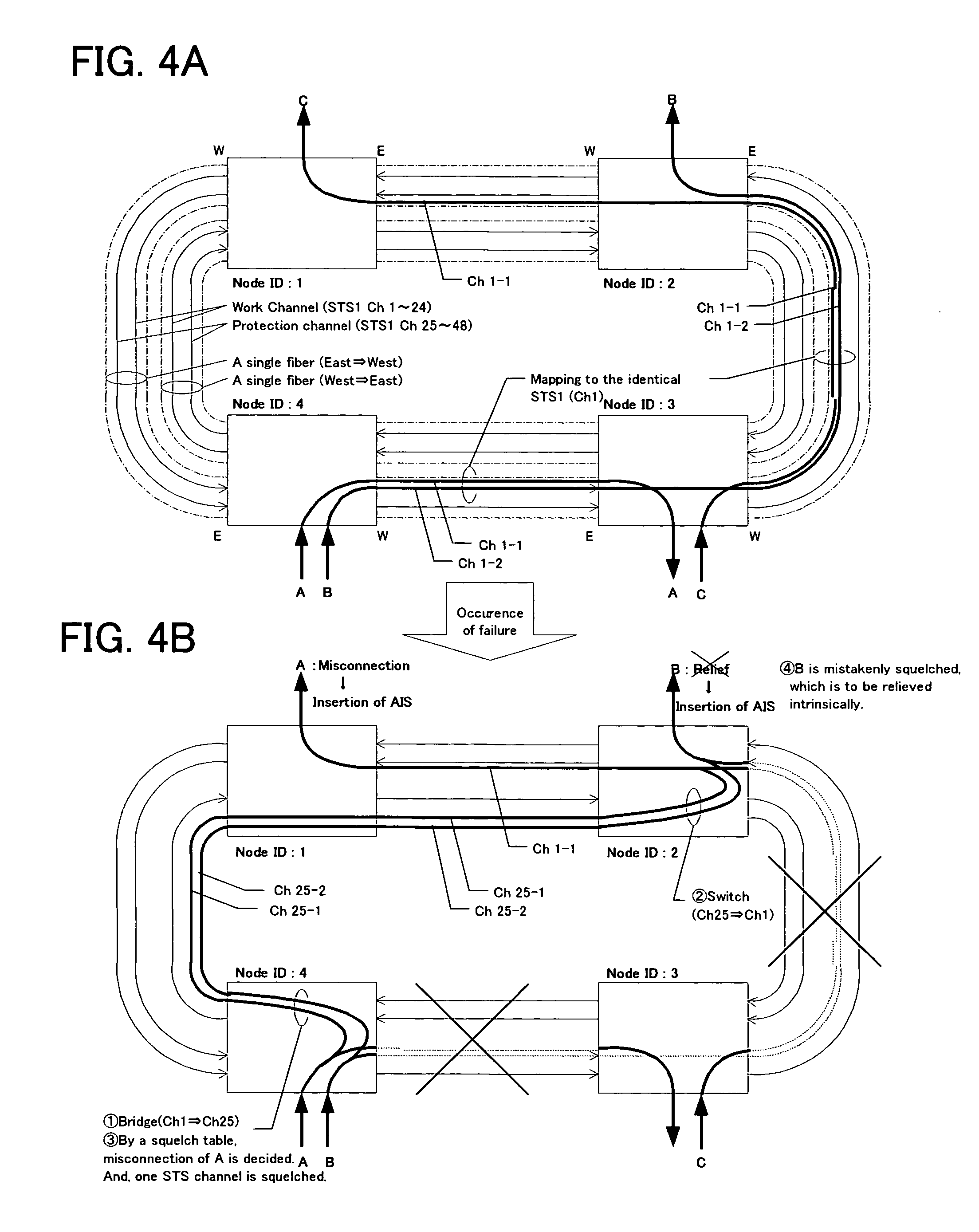
[0052]The preferred embodiment of the present invention is described hereinafter referring to the charts and drawings. FIG. 5 shows an explanation diagram illustrating switchover operation in the event of a failure in a bidirectional line switched ring (BLSR) network according to the present invention. As in the example shown in FIGS. 4A, 4B, there is considered the BLSR network in which four nodes are connected, and a case of the network condition shifted from the normal condition shown in FIG. 5A to a communication disabled condition, caused by a line failure between node ID2 and node ID3 and a line failure between node ID3 and node ID4.

[0053]In the normal condition shown in FIG. 5A, similar to the case shown in FIG. 4A, lower-order VT channels A, B are mapped into higher-order STS channel 1 (Ch 1). Here, a difference from the example shown in FIG. 4A lies in that a source node ID is additionally transmitted in accordance with the present invention.

[0054]In this configuration of t...


PUM

PropertyMeasurementUnit
speedaaaaaaaaaa
transmission capacityaaaaaaaaaa
sizeaaaaaaaaaa

Abstract

A bidirectional line switched ring network which enables high-speed operation with improved reliability because of a reduced software processing load is disclosed, and the network includes a plurality of optical transmission equipment sets connected in a ring form, wherein optical transmission equipment provided in a node on the transmission side performs transmission to each lower-order channel by attaching a transmission-side node ID, and, optical transmission equipment provided in a node on the reception side collates the received transmission-side node ID with an expected value of the transmission-side node ID having been set in advance, and when the collation does not match, the optical transmission equipment in the node on the reception side prevents a misconnection in the event of a failure by inserting an alarm indication signal.

Description

FIELD OF THE INVENTION[0001]The present invention relates to a bidirectional line switched ring (BLSR) network constituted of a plurality of optical transmission equipment sets connected in a ring form, and more particularly a system in a synchronous optical network (SONET) with a mixed configuration of VT-and STS-level paths.BACKGROUND OF THE INVENTION[0002]In digital optical communication, with increasing transmission capacity in recent years, path relief is required in the event of a failure such as a transmission line break, as well as improved line use efficiency. The bidirectional line switched ring (BLSR) is employed as a means to meet the above requirement. At present, the BLSR is supported in the higher-order paths of an STS (synchronous transport signal) level (>51.8 Mbps) mainly for use in the backbone network. For the purpose of implementation in a subscriber system, it is necessary to provide the BLSR supporting the lower-order VT (virtual tributary) paths (>1.5 M...

Claims


Application Information

Patent Timeline
Patent Type & Authority Patents(United States)
IPC IPC(8): H04L12/437G02F1/00H04B10/07H04B10/27H04B10/275H04B10/29H04J3/00H04J3/08H04J3/14
CPCH04J3/085H04J2203/0042H04J2203/006Y10S370/907
Inventor YAMAGUCHI, NAOKITAZAWA, HIDEAKI
Owner FUJITSU LTD
Why Eureka
Try Eureka