In-situ gain calibration of radio frequency devices using thermal noise

a radio frequency device and gain calibration technology, applied in the direction of power management, transmission monitoring, receiver monitoring, etc., can solve the problems of large variation in amplifier gain, complex and expensive, and inability to build rf receivers in cmos, etc., to improve calibration accuracy and robust noise figure value

Active Publication Date: 2008-11-04
NVIDIA CORP
View PDF8 Cites 23 Cited by
  • Summary
  • Abstract
  • Description
  • Claims
  • Application Information

AI Technical Summary

Benefits of technology

[0006]According to a specific embodiment of the present invention, an exemplary method calibrates a radio frequency (“RF”) integrated circuit by first modeling an effective input noise power signal value using at least one noise figure (“NF”) value associated with an RF radio receiver, the effective input noise power signal being modeled for input into the RF radio receiver. Then, the method measures an output noise power signal from the RF radio receiver to form a measured output noise power signal value. The method continues by calibrating a gain of the RF radio receiver as a function of the effective input noise power signal value and the measured output noise power signal value. In one embodiment, measuring the output noise power signal includes generating thermal noise, and applying the thermal noise as a calibrating signal into the RF radio receiver. Note that both generating thermal noise and applying the thermal noise are repeatable so that the method can perform in-situ calibration of the gain. In at least one embodiment, the method measures an ambient temperature to determine a measured temperature for improving calibration accuracy, and then modifies a value of the at least one noise figure to form a modified noise figure value, which is based on the measured temperature. In particular, the modified noise figure value is a noise figure value that compensates for the effects of temperature on noise figures, thereby providing a more robust noise figure value for estimating the gain. Further, the method can adjust the gain in accordance with the modified noise figure value.

Problems solved by technology

Although these technologies provide for a relatively stable amplifier gain for an RF receiver over process, voltage and temperature (“PVT”), they are complex and expensive.
But gains of RF receivers built in CMOS are not as stable as the above-mentioned technologies over PVT, thereby leading to large variations in amplifier gain.
The step of calibrating the gain during production is associated with increased costs and test times. Further, this calibration occurs usually once; calibration is not performed post-production.
Other drawbacks of the conventional calibration techniques are that the initial calibration parameters do not generally account for either excursions in temperature or operational characteristics of the electrical components as those components age.

Method used


Image

  • In-situ gain calibration of radio frequency devices using thermal noise
  • In-situ gain calibration of radio frequency devices using thermal noise
  • In-situ gain calibration of radio frequency devices using thermal noise

Examples


Embodiment Construction

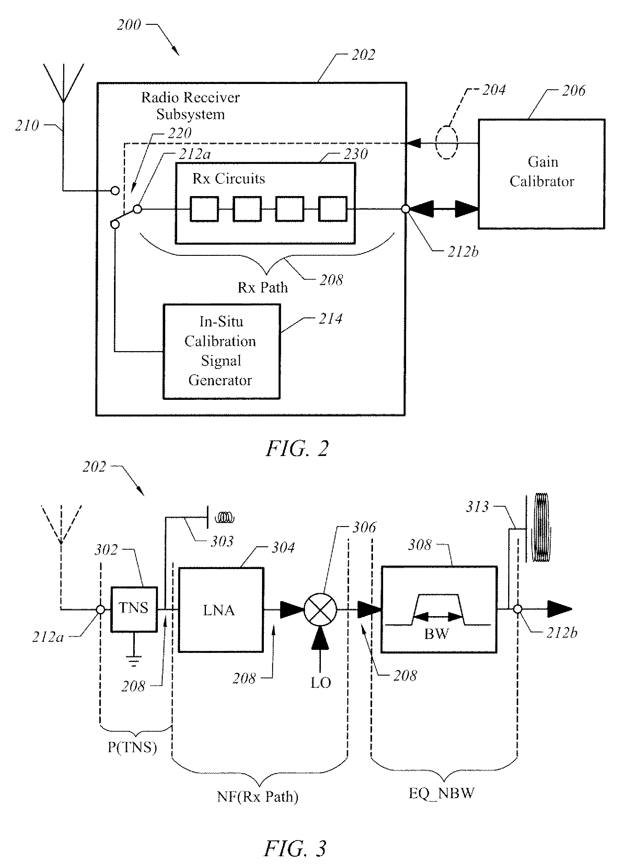
[0022]FIG. 2 is a block diagram illustrating an apparatus having at least two modes of operation, one of which is a mode for performing in-situ calibration of the gain of an RF receiver in accordance with one embodiment of the present invention. In this example, apparatus 200 is bi-modal in that it operates in one mode to receive communications as radio signals, such as those within the radio frequency (“RF”) bands, and operates in another mode to perform in-situ calibration independent of external calibration signals.

[0023]Apparatus 200 includes receiver (“Rx”) circuits 230 through which radio receiver amplification path (“Rx Path”) 208 propagates radio signals in a first mode (i.e., “receiver mode”). Rx circuits 230 influence the signal propagation characteristics of Rx Path 208. Examples of “Rx” circuits 230 include amplifiers (e.g., such as a Low-Noise Amplifier, or “LNA”), mixers, filtering circuitry, such as an intermediate frequency (“IF”) filter, analog-to-digital converters...


PUM


Abstract

An apparatus for calibrating gain of an radio frequency receiver (“Rx”) is disclosed to provide, among other things, a structure for performing in-situ gain calibration of an RF integrated circuit over time and / or over temperature without removing the RF integrated circuit from its operational configuration, especially when the gain of the RF integrated circuit is susceptible to variations in process, such as inherent with the CMOS process. In one embodiment, an exemplary apparatus includes a thermal noise generator configured to generate thermal noise as a calibrating signal into an input of an Rx path of an RF integrated circuit. The apparatus also includes a calibrator configured to first measure an output signal from an output of the Rx path, and then adjust a gain of the Rx path based on the thermal noise. In one embodiment, the thermal noise generator further includes a termination resistance and / or impedance.

Description

BRIEF DESCRIPTION OF THE INVENTION[0001]This invention relates generally to wireless communications, and more particularly, to performing in-situ calibration of a gain for a radio frequency (“RF”) radio receiver (“Rx”) using, for example, thermal noise as a calibrating signal.BACKGROUND OF THE INVENTION[0002]Bipolar and Bipolar Complementary Metal Oxide Semiconductor (“BiCMOS”) are examples of processing technologies used to manufacture RF integrated circuits (“ICs”) that include RF receivers. Although these technologies provide for a relatively stable amplifier gain for an RF receiver over process, voltage and temperature (“PVT”), they are complex and expensive. Complementary Metal Oxide Semiconductor (“CMOS”) processing technology, which is simpler and less costly, has been implemented to avoid the complexities and costs of those technologies to manufacture RF ICs. But gains of RF receivers built in CMOS are not as stable as the above-mentioned technologies over PVT, thereby leadi...

Claims


Application Information

Patent Timeline
Patent Type & Authority Patents(United States)
IPC IPC(8): H04B1/06
CPCH04B17/21H04W52/367H04B17/0085H04W52/16H04W52/40
Inventor KUO, TIMOTHY C.KERAMAT, MANSOURLIU, EDWARD WAI YEUNG
Owner NVIDIA CORP
Why Eureka
Try Eureka