Retinal implant with improved implantation and working properties

a technology of retinal implants and working properties, applied in the field of retinal implants, can solve the problems of increasing the risk of future pathological tissue changes, increasing the difficulty of surgical interventions, and difficulty in re-explantation,

Inactive Publication Date: 2008-11-04
PIXIUM VISION SA
View PDF8 Cites 24 Cited by
  • Summary
  • Abstract
  • Description
  • Claims
  • Application Information

AI Technical Summary

Benefits of technology

[0008]It is therefore an object of the present invention to provide a retinal implant in which the connection between the internal functional unit IGF and at least one external functional unit (AGF, EPF) does not interrupt the optical path between the lens and the extrafoveal region of the retina, and in which this connection is wireless or can be mechanically separated during implantation.
[0010]Because the signal path extends through the sclera of the eye, inside the eye socket bounded by the conjunctiva, the optical path from the lens to the retina outside the foveal region remains free. The separability of the signal path permits separate implantability of the component implanted inside the eye and the component implanted outside the eye in the eye socket.

Problems solved by technology

This mechanical connection makes the surgical interventions significantly more difficult since, when implanting the AGF in the lenticular capsule envelope, it is also necessary to make an opening in the lenticular capsule wall and to transfer the IGF, with the microcable connection, through this opening into the vitreous chamber.
This entails additional risk factors such as: mechanical destabilisation of the lenticular capsule envelope by the additional opening; mechanical stress on the implant components, including the microcable; lengthening of the implantation time; increase in the risk of future pathological tissue changes, which may make the implant function or further surgical interventions (such as e.g. re-explantation) difficult or impossible.
This can have a detrimental effect both on the function of the implant system and on sight, as well as on the medical inspectability of the vitreous chamber.
As the signal processing effort rises, especially in the case of retinal implants, when the number of microcontacts increases, the mass and energy demand of the microelectronic components rises significantly, so that in this context a limit for intraocularly implantable functional units is rapidly reached and the desired functional quality of the implant is thereby substantially restricted.

Method used


Image

  • Retinal implant with improved implantation and working properties
  • Retinal implant with improved implantation and working properties
  • Retinal implant with improved implantation and working properties

Examples


Embodiment Construction

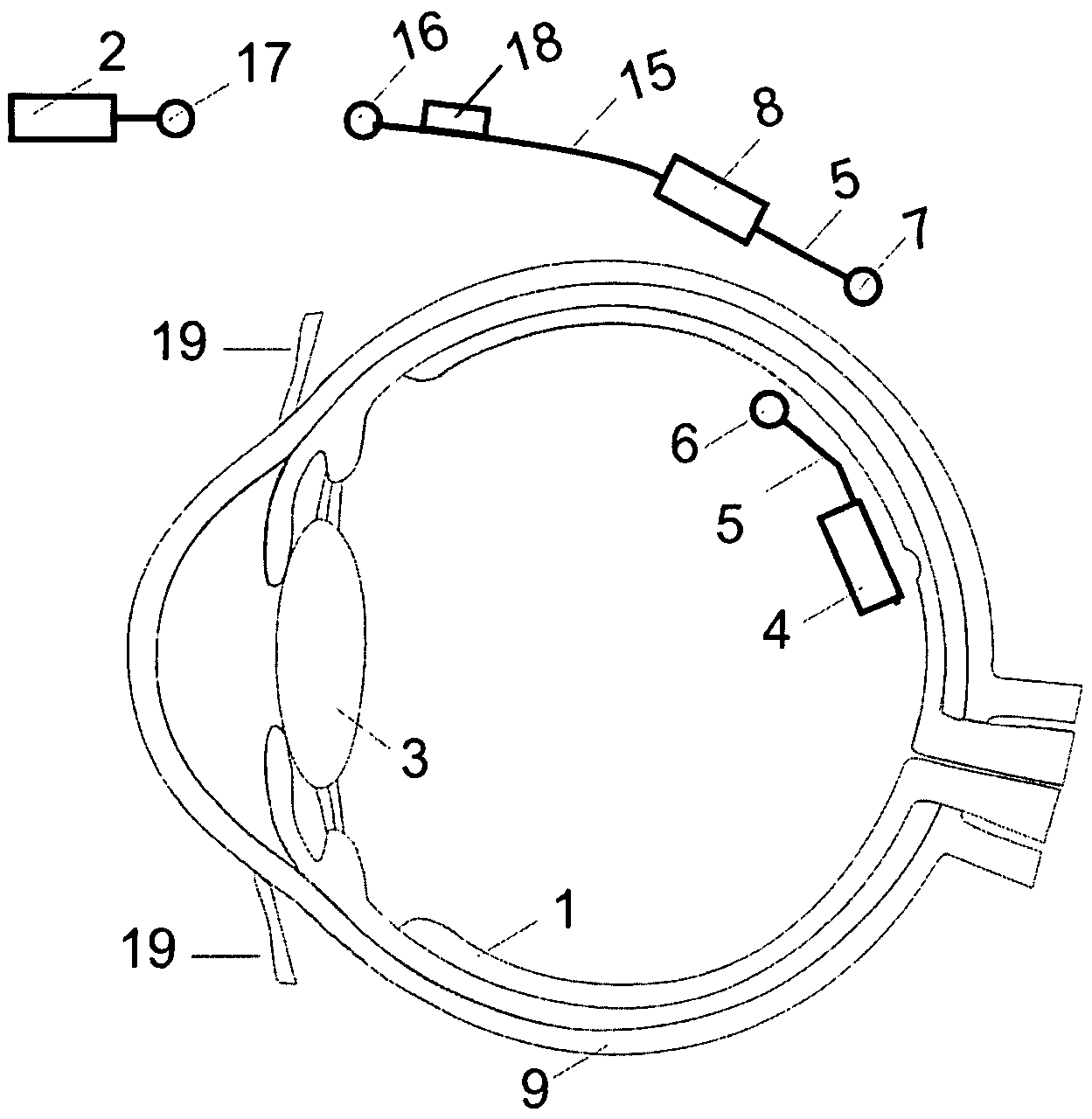
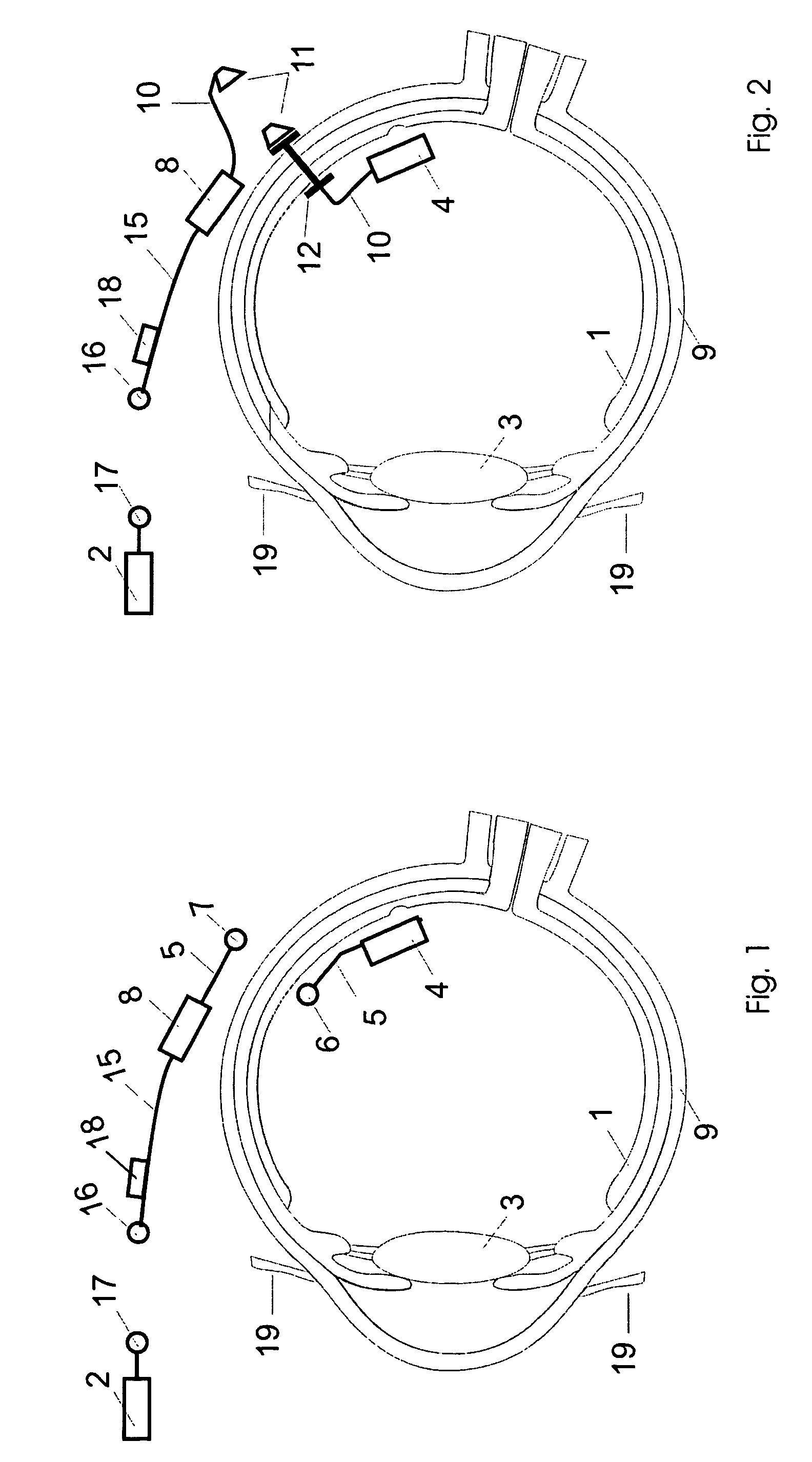
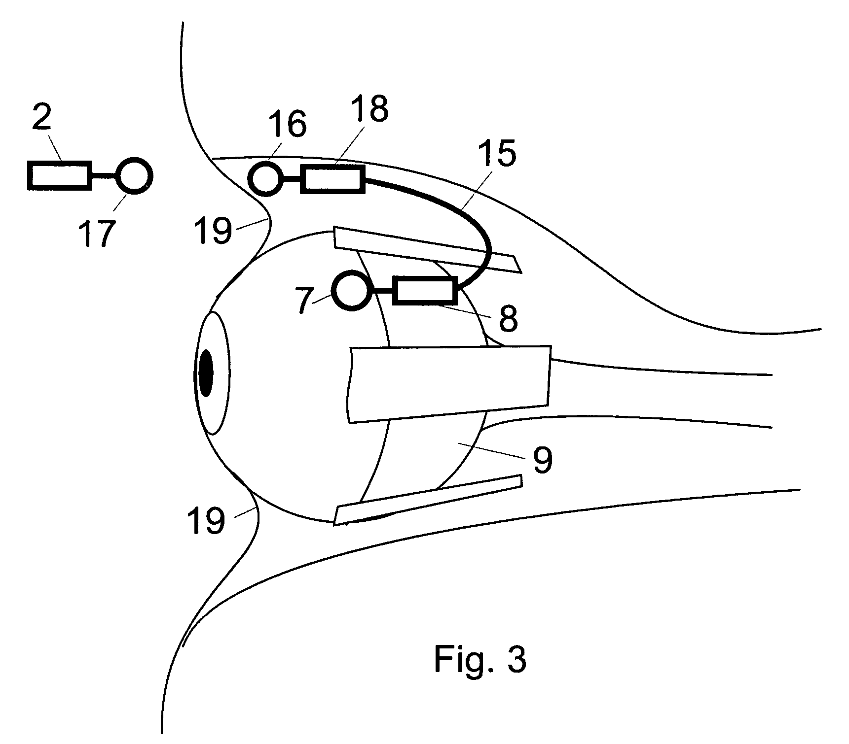
[0015]FIG. 1 represents a retinal implant for patients having a degenerative disease of the retina 1, in which the functional unit(EPF) 2 present outside the body is positioned in the head region (e.g. on the side of a spectacle frame with normal spectacle function), in such a way that the optical beam path between viewed objects and the retina 1 is impaired neither by functional units directly in front of the eye nor by functional units in the anterior eye segment, including the intraocular lens (IOL) 3, and in such a way that, in particular, patients can thereby use their residual vision which may still remain (e.g. in the extrafoveal field of view in the case of macular degeneration), in addition to the implant function.

[0016]In a retinal implant according to the invention, the functional unit IGF 4 positioned inside the vitreous chamber is designed as a microcontact foil having associated microelectronics, a microcable S and at least one coil 6, and is fastened close to the reti...


PUM


Abstract

A retinal implant has at least one functional unit positioned internally inside an eye and at least one functional unit positioned externally outside the eye and at least one functional unit positioned outside the eye, which are separably connected to one another via a signal path in a manner designed for signal or data transmission. The patient's residual vision which may still remain is preserved because the signal path extends through the sclera of the eye and does not incorporate the anterior eye section.

Description

CROSS-REFERENCE TO RELATED APPLICATION[0001]This application is related to U.S. patent application Ser. No. 10 / 056,208 filed Jan. 28, 2002, and draws priority from German Application No. 10154700.5, filed on Nov. 9, 2001, both of which are incorporated herein by reference in their entirety.BACKGROUND OF THE INVENTION[0002]The present invention relates to a retinal implant.[0003]An implant according to the generic type is known from U.S. Pat. No. 5,935,155. This document proposes that a functional unit (IGF) positioned inside the vitreous chamber be connected to an externally positioned functional unit (EPF) via wireless coupling of two coils. The coil of the internal functional unit is in this case arranged in the lens behind the iris.[0004]In addition to the surgical intervention on the vitreous body for implanting the functional unit (IGF) positioned inside the vitreous chamber, a second surgical intervention is necessary in the anterior eye section for implanting the coil or a se...

Claims


Application Information

Patent Timeline
Patent Type & Authority Patents(United States)
IPC IPC(8): A61N1/00A61N1/36
CPCA61N1/36046A61F2250/0002
Inventor ECKMILLER, ROLF
Owner PIXIUM VISION SA
Why Eureka
Try Eureka