Color image sensor unit and image reading apparatus using the sensor unit and control method therefor

a color image sensor and image reading technology, applied in the direction of optical radiation measurement, instruments, spectrometry/spectrophotometry/monochromators, etc., can solve the problems of lowering the s/n ratio of the b component signal, and difficulty in performing the superimposition of the rgb signal by the delay processing in the unit of one line, so as to prevent color misalignment of the image signal

Active Publication Date: 2008-11-11
CANON COMPONENTS INC
View PDF12 Cites 20 Cited by
  • Summary
  • Abstract
  • Description
  • Claims
  • Application Information

AI Technical Summary

Benefits of technology

[0044]According to the present invention, light emitting elements for emitting light of respective color components, and arrays of sensors for detecting image signals of the respective color components are provided, so as to make it possible to adjust the level of output signals from the respective sensors.
[0045]Further, according to the present invention, even when the reading speed in the subscanning direction is changed, it is possible to obtain an effect of preventing color misalignment of an image signal read from an original.

Problems solved by technology

However, when the sensor array shown in FIG. 17 is used, following problems arise.
Thus, there is a problem that the noise component contained in the B component signal is also amplified by such signal amplification, and thereby the S / N ratio of the B component signal is lowered as compared with the R component signal.
This makes it difficult to perform superimposition of RGB signals by the delay processing in the unit of one line.

Method used


Image

  • Color image sensor unit and image reading apparatus using the sensor unit and control method therefor
  • Color image sensor unit and image reading apparatus using the sensor unit and control method therefor
  • Color image sensor unit and image reading apparatus using the sensor unit and control method therefor

Examples


embodiment 1

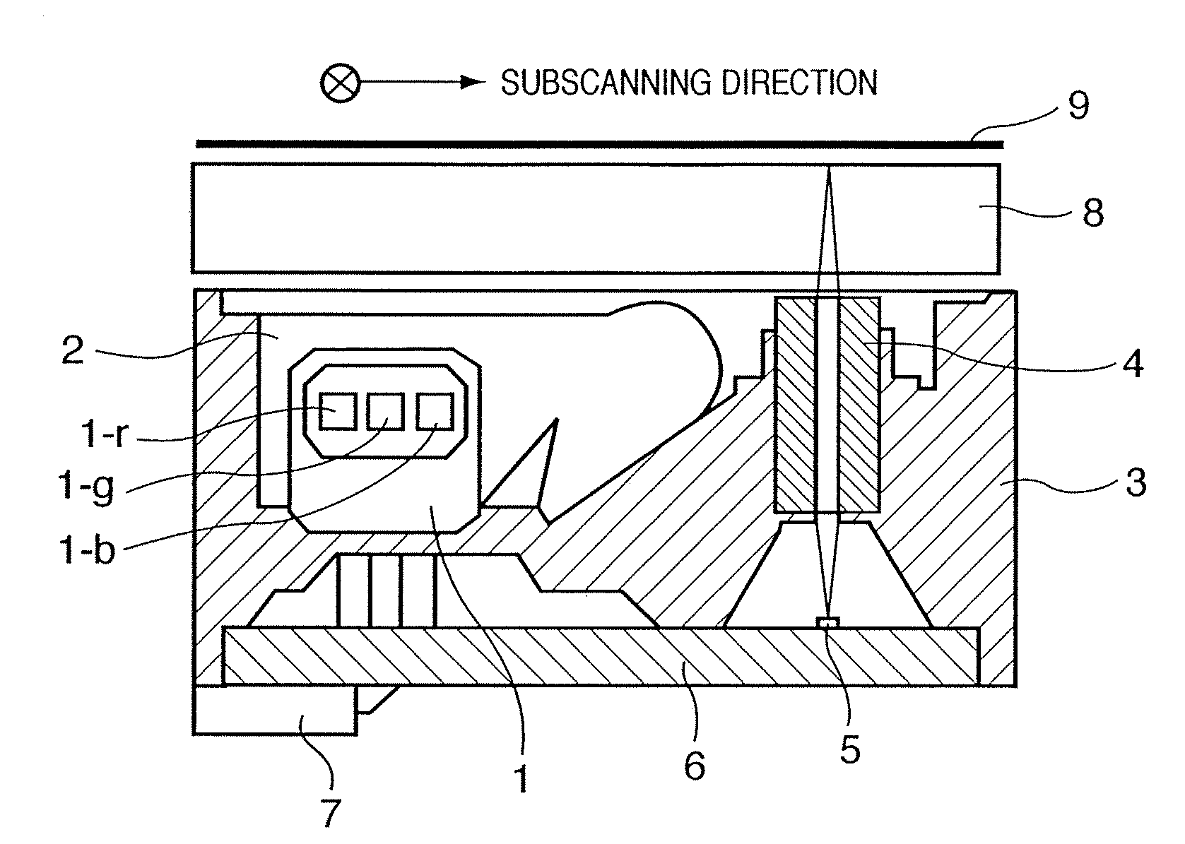
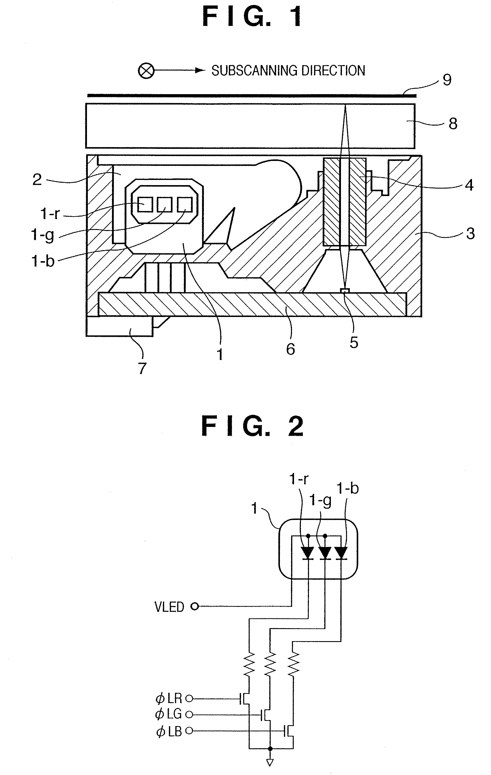
[0075]FIG. 1 is a block diagram showing a constitution of a color contact image sensor (CIS) unit according to an embodiment of the present invention. Note that the CIS unit according to the present embodiment comprises at least a light source 1, a light guide member 2 for illuminating in the width direction of an original with light from the light source 1, and a sensor array 5 for detecting reflected light from the original.

[0076]In FIG. 1, the light source 1 is a light source for illuminating the original 9, and light emitting elements 1-r, 1-g and 1-b for respectively emitting light having wavelengths of primary three colors (RGB) are mounted to the light source 1. The light emitted from the light source 1 is introduced into the inside of the light guide member 2 arranged in the width direction of the original, and guided in the perpendicular direction (main scanning direction) in FIG. 1, so as to irradiate as linear light flux from a light emitting section provided for the ligh...

embodiment 2

[0103]Next, an embodiment 2 according to the present invention is described with reference to FIG. 8.

[0104]A constitution of a color sensor according to the present embodiment 2 is the same as that of the above described embodiment 1, but is different in the method for driving each of three light emitting elements 1-r, 1-g and 1-b which constitute the light source, that is, different in the light emission start timing. The three light emitting elements 1-r, 1-g and 1-b have an independent drive circuit, respectively. The lighting start timing and the lighting period of the three light emitting elements are independently controlled, during one operating cycle TW, by drive signals φLR, φLG and φLB which correspond to the three light emitting elements, respectively. For example, in the example shown in FIG. 8, the drive signal φLR of the light emitting element 1-r is turned on after a period TNR from the rise time of the signal SP, and is set at a high level during a period TWR. This m...

embodiment 3

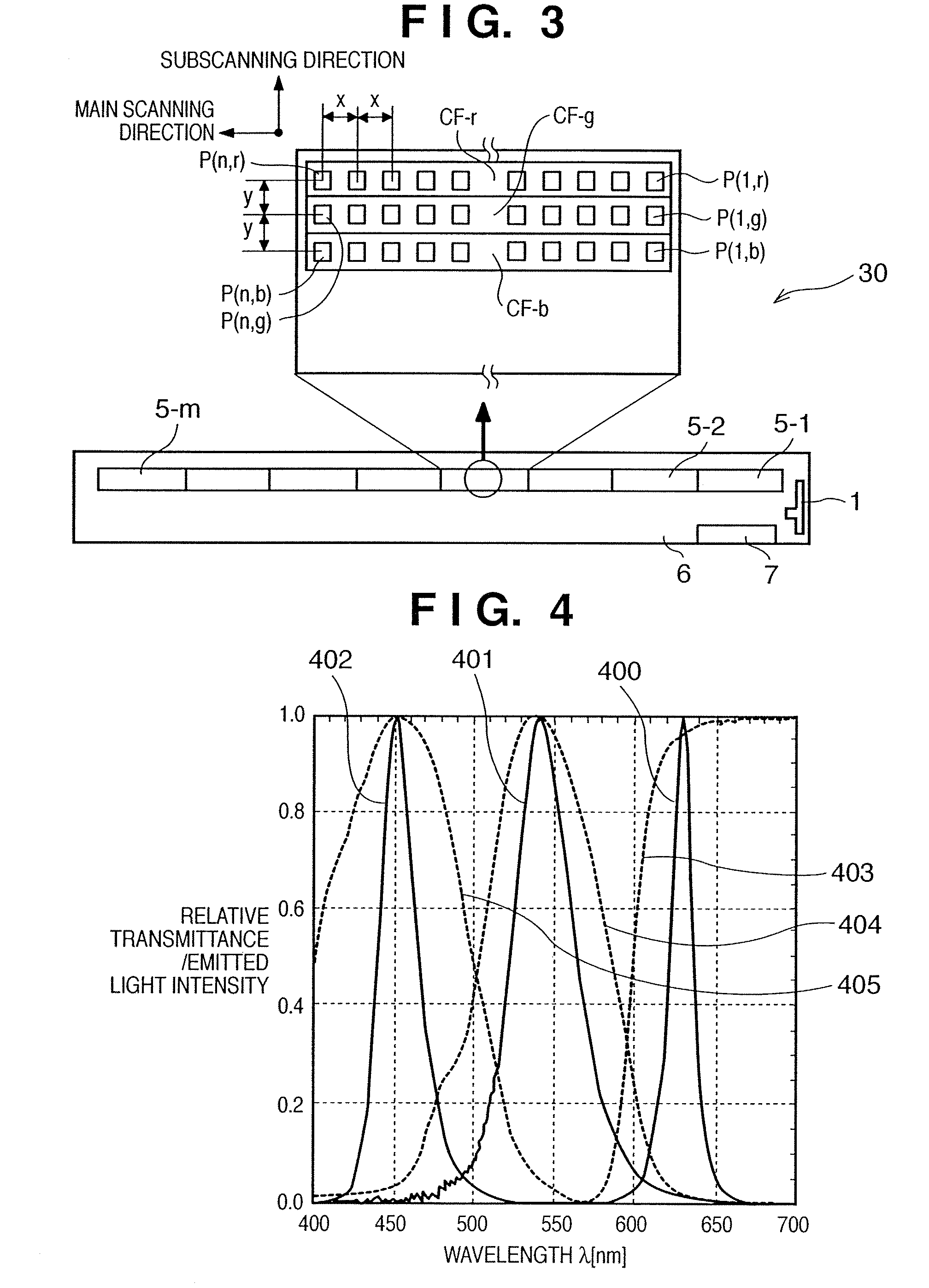
[0117]By using the driving method of the light source according to the above described embodiment 2, the interval y between the pixel arrays in the subscanning direction can be arbitrarily set independently of the interval x between the pixels. In the case where the interval y between the pixel arrays is set smaller than the interval x between the pixels, the inter-line delay processing for correcting the color misalignment can be eliminated, even when the reading operation is performed on the basis of the basic resolution of sensors which is determined by the interval x between the pixels.

[0118]FIG. 9D is a figure showing an operation timing when the resolution in the main scanning direction is equal to the resolution in the subscanning direction. For example, a case where the interval y between the pixel arrays is set to ½ of the interval x between the pixels is considered. Also in this case, the delay periods TNR, TNG and TNB which determine the lighting start timings of the resp...


PUM


Abstract

A color image sensor which uses a sensor array that has, as a lighting light source, 3-color light emitting elements capable of independently controlling light emitting timings respectively and at least three pixel arrays respectively constituted by a plurality of pixels, respective pixel arrays being comprising color filters having different transmitting wavelength regions from each other, and which independently controls the lighting start and lighting period of each light emitting element, whereby it is possible to prevent color misalignment in an output image signal and regulate the image signal level of each color component.

Description

TECHNICAL FIELD[0001]The present invention relates to a color image sensor unit provided for an image reading section which reads reflected light from the surface of an original, an image reading apparatus using the color image sensor unit, and a method for controlling the image reading apparatus.BACKGROUND ART[0002]Conventionally, in image reading apparatuses, such as an image scanner and copying machine, a contact image sensor (hereinafter abbreviated as CIS) which is arranged close to an original so as to read it without magnification, has been used as an image sensor which optically reads image information of the original and converts the read information to an electric signal.[0003]FIG. 13A and FIG. 13B depict views for explaining the CIS unit. FIG. 13A depicts a sectional view of the CIS unit, and FIG. 13B depicts a drive circuit of a light source in the CIS unit.[0004]Light emitted from a light source 21 arranged on the end surface of a light guide member 22, is made incident...

Claims


Application Information

Patent Timeline
Patent Type & Authority Patents(United States)
IPC IPC(8): H04N1/028G01J1/32H01L27/00G01J3/02G01J3/28G01J3/50G01J3/51H04N1/04H04N1/193H04N1/48
CPCG01J3/02G01J3/0256G01J3/2803G01J3/50G01J3/501G01J3/51G01J3/513H04N1/02815H04N1/02835H04N1/486H04N1/193H04N23/74H04N25/531H04N23/84H04N1/028H04N1/04
Inventor KAIHOTSU, TAKAHIRO
Owner CANON COMPONENTS INC
Why Eureka
Try Eureka