Particle beam irradiation equipment and particle beam irradiation method

a particle beam and irradiation equipment technology, applied in the field of particle beam irradiation equipment and particle beam irradiation method, can solve the problems of difficult to always realize irradiation with a long range and high dose uniformity, and achieve the effect of high dose uniformity

Active Publication Date: 2008-11-11
HITACHI LTD
View PDF9 Cites 159 Cited by
  • Summary
  • Abstract
  • Description
  • Claims
  • Application Information

AI Technical Summary

Benefits of technology

[0009]It is an object of the present invention to provide particle beam irradiation equipment and a particle beam irradiation method, which can provide a long range of a charged particle beam in the patient body and ensure high dose uniformity at any irradiation field size.
[0011]Since the second scatterers can be optionally placed in the first position and the second position in the direction of travel of the charged particle beam, it is possible to change the position, at which the second scatterer is placed, depending on the size of an irradiation field to be formed. At any field size, therefore, a long range of the charged particle beam can be obtained in the patient body and higher dose uniformity can be ensured in irradiation. For example, when a comparatively large irradiation field is formed, the second scatterer is placed at the first position, and when a comparatively small irradiation field is formed, the second scatterer is placed at the second position. In either case, the second scatterer can be placed at an optimum position in consideration of balance between a longer range and higher dose uniformity. As a result, irrespective of the field size, the irradiation of the charged particle beam can be realized with a long range and high dose uniformity over the whole of the formable irradiation field.

Problems solved by technology

Accordingly, it has been difficult to always realize irradiation with a long range and high dose uniformity regardless of the field size.

Method used


Image

  • Particle beam irradiation equipment and particle beam irradiation method
  • Particle beam irradiation equipment and particle beam irradiation method
  • Particle beam irradiation equipment and particle beam irradiation method

Examples


first embodiment

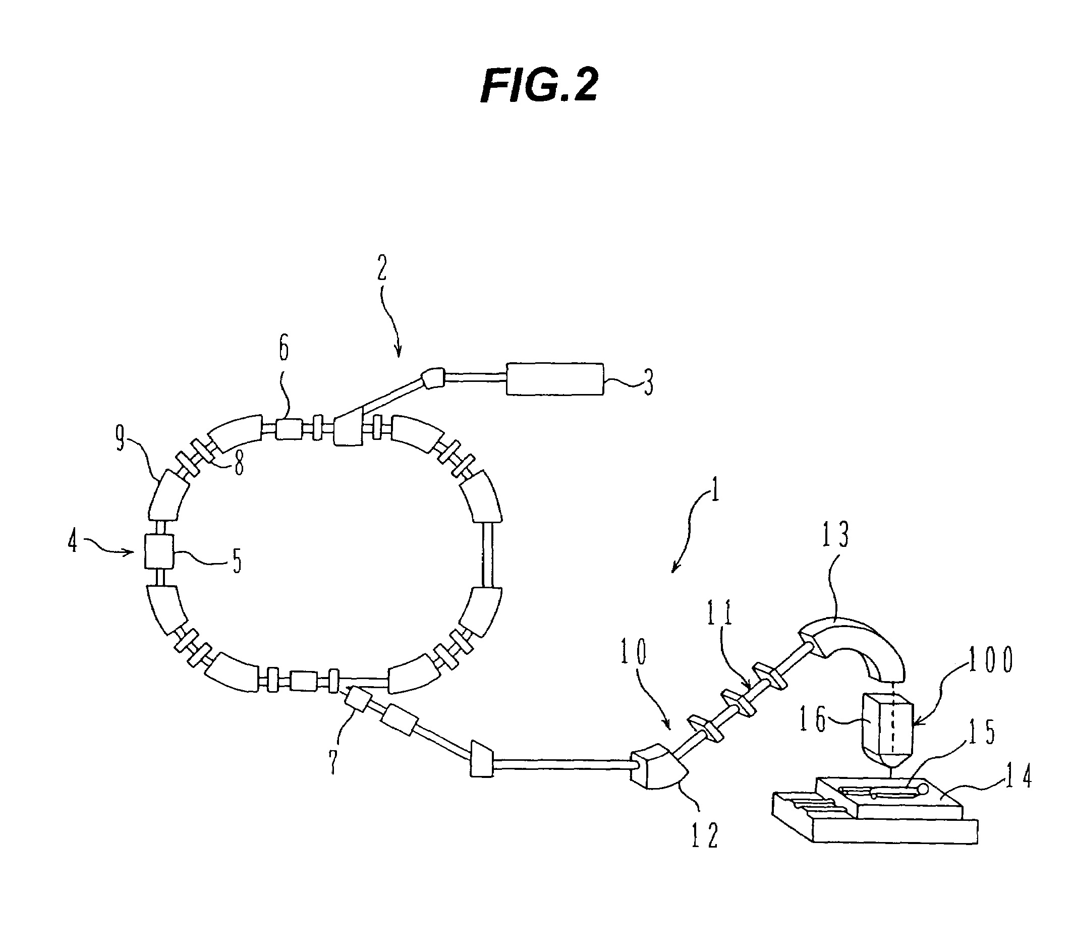
[0021]Particle beam irradiation equipment (particle beam treatment equipment) as one preferable embodiment of the present invention will be described below with reference to FIG. 2. Particle beam irradiation equipment 1 of this embodiment comprises charged particle beam generation equipment 2 and irradiation field producing equipment (irradiation nozzle) 100. The charged particle beam generation equipment 2 comprises an ion source (not shown), a pre-accelerator 3, and a synchrotron 4. Ions (e.g., proton ions (or carbon ions)) generated by the ion source are accelerated by the pre-accelerator 3 (e.g., a linear accelerator (LINAC)). An ion beam (charged particle beam) emitted from the pre-accelerator 3 enters a synchrotron 4. The ion beam is accelerated in the synchrotron 4 by being given with energy in the form of RF-power applied from an RF-accelerating cavity 5. After energy of the ion beam circulating in the synchrotron 4 has been increased up to a setting level, a radio frequency...

second embodiment

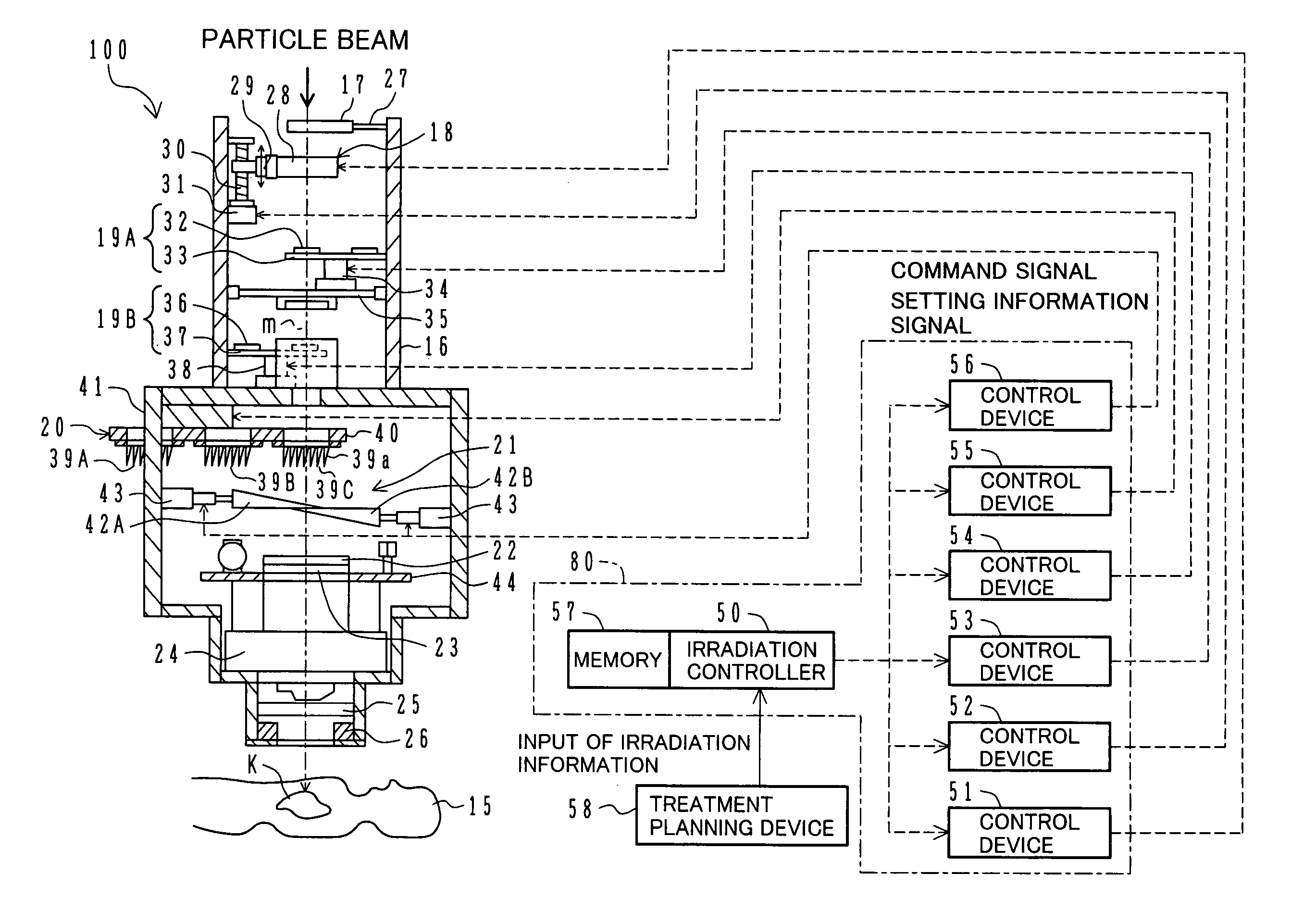
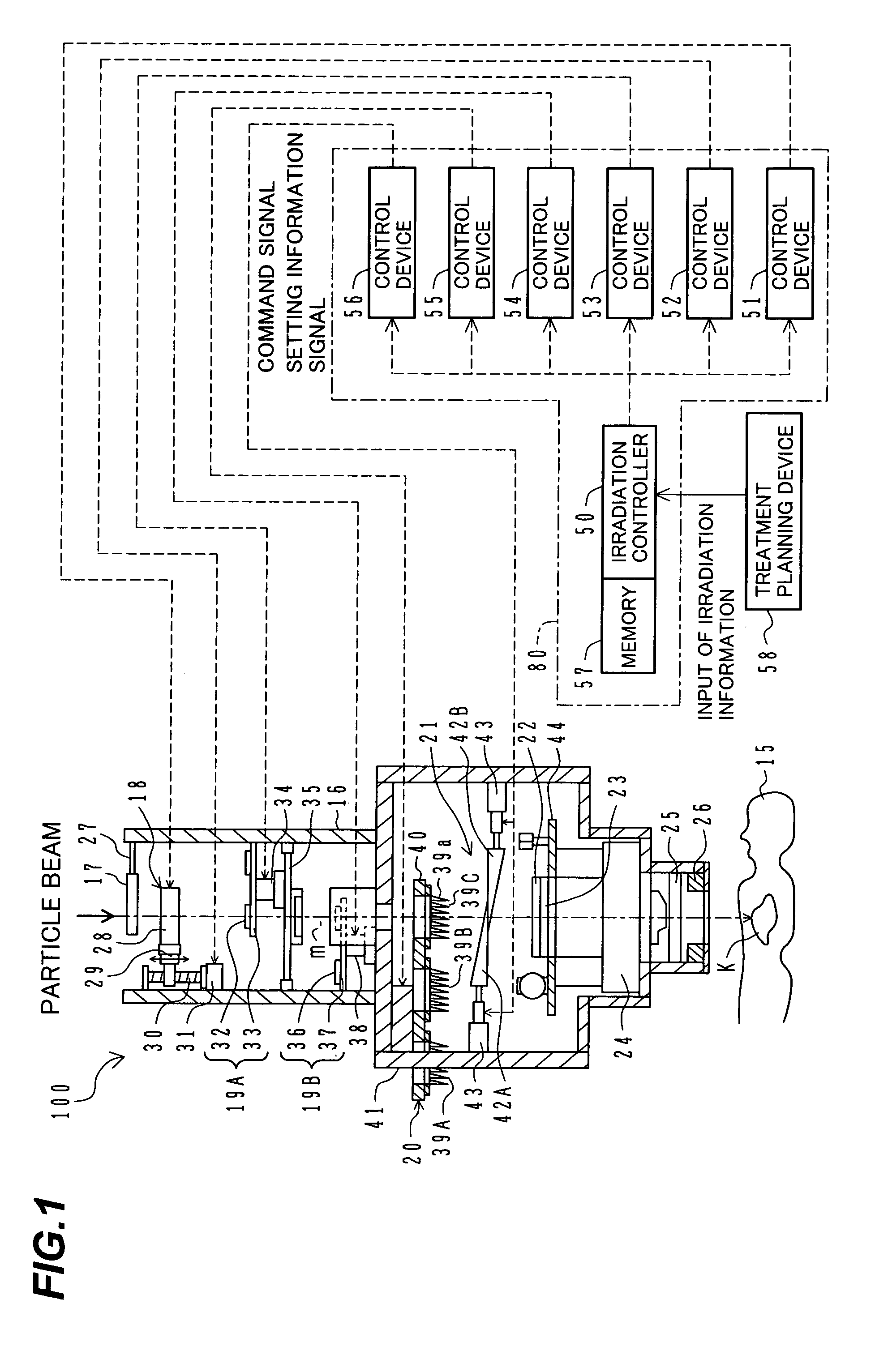
[0083]Particle beam irradiation equipment (particle beam treatment equipment) according to a second embodiment of the present invention will be described below. In the particle beam irradiation equipment of this second embodiment, the irradiation nozzle 100 in the particle beam irradiation equipment 1 shown in FIG. 1 is replaced with an irradiation nozzle 100A shown in FIG. 6.

[0084]In FIG. 6, the irradiation nozzle 100A includes one unit of second scatterer device 60, which is movable in the direction of the beam axis m, in stead of the two-stage second scatterer devices 19A, 19B which are fixed at respective upstream and downstream positions in spaced relation. The irradiation nozzle 100A further includes a second scatterer moving device 64.

[0085]The second scatterer device 60 is adapted for both the cases of a large field size and a small field size (i.e., usable regardless of the field size), and includes second scatterers 61. Similarly to the second scatterers 32 and 36 in the f...


PUM


Abstract

Particle beam irradiation equipment and a method of adjusting irradiation nozzle, which can ensure a long range and high dose uniformity at any field size are provided. The particle beam irradiation equipment comprises charged particle beam generation equipment and an irradiation nozzle for irradiating a charged particle beam extracted from the charged particle beam generation equipment to an irradiation target. The irradiation nozzle comprises a first scatterer device including a first scatterer for spreading out the charged particle beam into a Gaussian-like distribution, and multiple stages of second scatterer devices including second scatterers for producing a uniform intensity distribution of the charged particle beam having been spread out into a Gaussian-like distribution by the first scatterer. For forming irradiation fields having sizes different from each other, the second scatterer devices are disposed downstream of the first scatterer device in the direction of travel of the charged particle beam at the spacing depending on the difference in the field size.

Description

BACKGROUND OF THE INVENTION[0001]1. Field of the Invention[0002]The present invention relates to particle beam irradiation equipment. More particularly, the present invention relates to particle beam irradiation equipment, which is suitably applied to particle beam treatment for irradiating a charged particle beam of, e.g., proton ions or carbon ions, to a tumor for treatment, material irradiation equipment for irradiating a charged particle beam to materials, food irradiation equipment for irradiating a charged particle beam to foods, and radio isotope producing equipment utilizing a charged particle beam, and also relates to a method of adjusting irradiation field producing equipment used in the particle beam irradiation equipment.[0003]2. Description of the Related Art[0004]Known particle beam treatment equipment comprises charged particle beam generation equipment, an ion beam transport system, and rotating irradiation equipment. The charged particle beam generation equipment in...

Claims


Application Information

Patent Timeline
Patent Type & Authority Patents(United States)
IPC IPC(8): A61N5/00H01J33/00G21K3/00A61N5/10G21K5/04
CPCA61N5/10G21K5/04A61N2005/1087A61N2005/1095A61N2005/1096
Inventor FUJIMAKI, HISATAKAMATSUDA, KOJIYANAGISAWA, MASAKIAKIYAMA, HIROSHI
Owner HITACHI LTD
Why Eureka
Try Eureka