Scanning exposure method for photo-etching machine

A scanning exposure and lithography technology, which is applied in microlithography exposure equipment, photolithography process exposure devices, etc., can solve the problems of inability to change dose uniformity-slit integral uniformity, etc., to improve dose uniformity, improve System performance, the effect of improving uniformity

Active Publication Date: 2010-12-29
SHANGHAI MICRO ELECTRONICS EQUIP (GRP) CO LTD
View PDF0 Cites 0 Cited by
  • Summary
  • Abstract
  • Description
  • Claims
  • Application Information

AI Technical Summary

Problems solved by technology

However, these methods are all based on unidirectional scanning exposure methods, which can only improve the dose uniformity of the exposure field in the scanning direction (Y direction), but cannot change the dose uniformity in the non-scanning direction (X direction)-slit integral uniformity

Method used


Image

  • Scanning exposure method for photo-etching machine
  • Scanning exposure method for photo-etching machine
  • Scanning exposure method for photo-etching machine

Examples


Embodiment approach

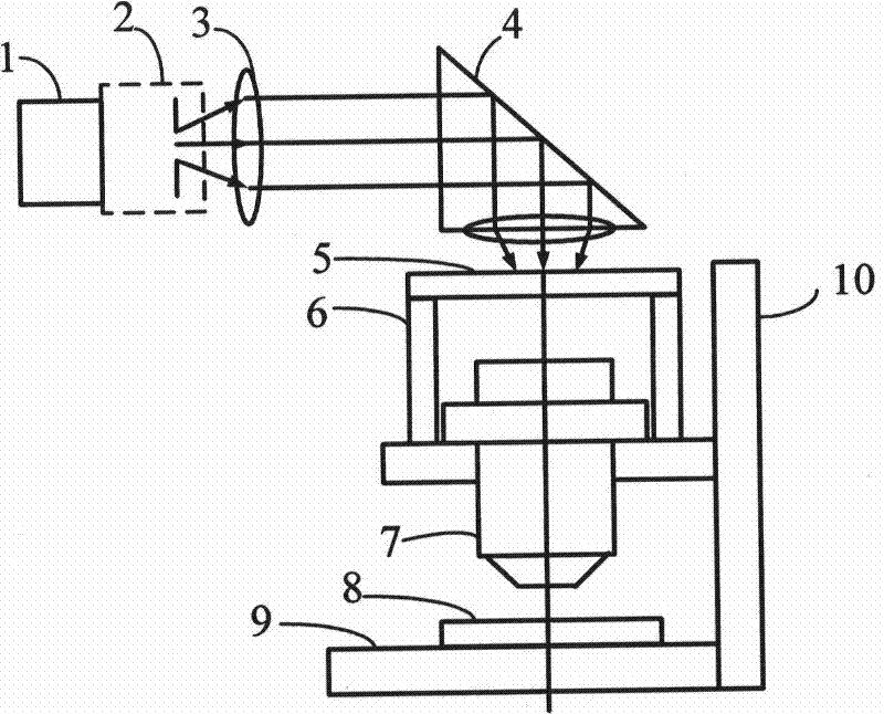
[0025] see figure 1 , figure 1 It is a schematic diagram of a photolithography apparatus used in the photolithography scanning exposure method in the embodiment of the present invention. The light source 1 passes through the variable slit 2 provided on the lithography machine, passes through the illumination lens group formed by the illumination lens 3 and the refracting mirror 4, and the field of view contour formed by the variable slit 2 is projected onto the mask surface 5 where the mask table 6 is located. .

[0026] In this embodiment, two mutually orthogonal directions are set on a plane perpendicular to the optical axis, and the two orthogonal directions are respectively defined as the X axis and the Y axis, and the X direction, the Y direction and the chief ray propagation direction The inverse directions of these three directions satisfy the right-hand rule. The planes where the silicon plane 8, the mask surface 5 and the variable slit 2 of the photolithography mac...


PUM


Abstract

The invention provides a scanning and exposure method of a photoetching machine. The method comprises the following steps: two directions which are mutually orthogonal are arranged on a silicon plain of the photoetching machine and the silicon plain is divided into a plurality of exposure field areas, a changeable narrow slit is arranged on the photoetching machine, the changeable narrow slit is provided with cutting lips in the two mutually orthogonal directions, scanning and exposure are carried out on one direction of the exposure field area and then on the other direction of the same exposure field area; when the scanning and exposure are carried out on one direction of the exposure field area, the cutting lips of the changeable narrow slit in the direction are gradually opened to themaximum and then gradually folded to be closed. In the invention, the scanning and exposure are first carried out on one direction of the exposure field area and then on the other direction of the same exposure field area, therefore, dose uniformity of both X direction and Y direction of the exposure field areas are improved, thus improving system performance of exposure dose and uniformity of photoetching line width.

Description

technical field [0001] The invention relates to a method for operating a semiconductor device, in particular to a scanning exposure method for a photolithography machine. Background technique [0002] The core of modern microelectronics technology is integrated circuit production, and the development of integrated circuit production must be supported by semiconductor equipment. In the current integrated circuit production equipment, lithography equipment occupies the most core position. After the lithography technology has gone through several major technical development stages of contact type, proximity type, projection type, scanning type and stepping type, it transitions to stepping and scanning type. [0003] The three core indicators of lithography machines are line width uniformity, overlay accuracy and productivity. Line width uniformity is an important core index of a lithography machine, and the performance of the dose system and the performance of the focal plane ...

Claims


Application Information

Patent Timeline
Patent Type & Authority Patents(China)
IPC IPC(8): G03F7/20
Inventor 张俊
Owner SHANGHAI MICRO ELECTRONICS EQUIP (GRP) CO LTD
Why Eureka
Try Eureka