Method of implanting a substrate and an ion implanter for performing the method

A technology of ion implantation and substrate, applied in the direction of instruments, scientific instruments, solid waste removal, etc., can solve the problem of slow scanning speed and achieve good dose uniformity

Inactive Publication Date: 2010-01-20
APPLIED MATERIALS INC
View PDF8 Cites 0 Cited by
  • Summary
  • Abstract
  • Description
  • Claims
  • Application Information

AI Technical Summary

Problems solved by technology

By controlling the speed of this mechanical movement, the dose uniformity across the wafer surface is guaranteed in the direction of the mechanical movement of the wafer, but the mechanical movement is always much slower than the beam scanning speed

Method used


Image

  • Method of implanting a substrate and an ion implanter for performing the method
  • Method of implanting a substrate and an ion implanter for performing the method
  • Method of implanting a substrate and an ion implanter for performing the method

Examples


Embodiment Construction

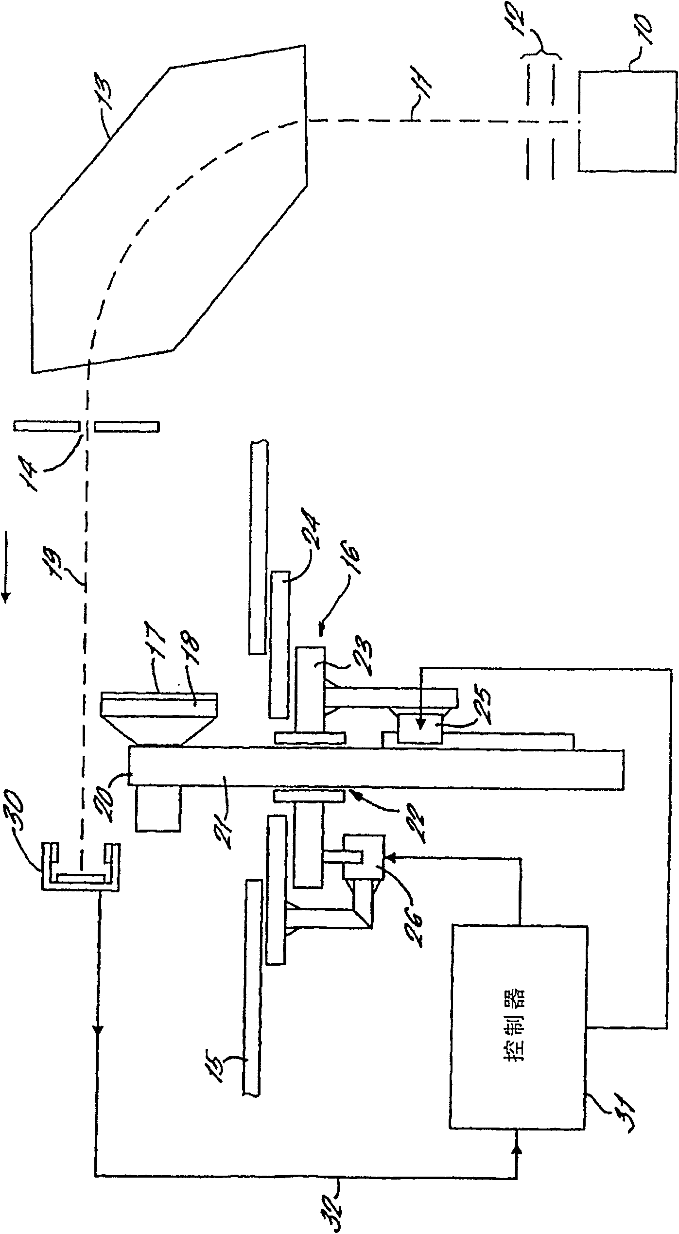
[0038] refer to figure 1 , the illustrated ion implanter includes an ion source 10 from which an ion beam 11 is extracted via an extraction electrode 12 . The ion beam 11 then passes through the mass analyzer magnet 13, passing through the mass splitting slit 14, and ions exiting the mass analyzer magnet 13 are sorted out of the beam with the desired mass corresponding to the ion containing the atomic nuclides to be implanted. ion. As is well known, the beam ions selected for implantation may be atomic ions containing only the atomic nuclides to be implanted, molecular ions including the desired atomic nuclides, or multiple atoms or molecules of the desired nuclides cluster ions.

[0039] These components of ion implanters are standard and well known to those working in the ion implantation art. Together, these components form an ion beam generator that generates a beam of ions containing the desired atomic species for implantation into the semiconductor wafer.

[0040] Th...


PUM


Abstract

An implanter provides two-dimensional scanning of a substrate relative to an implant beam so that the beam draws a raster of scan lines on the substrate. The beam current is measured at turnaround points off the substrate and the current value is used to control the subsequent fast scan speed so as to compensate for the effect of any variation in beam current on dose uniformity in the slow scan direction. The scanning may produce a raster of non-intersecting uniformly spaced parallel scan lines and the spacing between the lines is selected to ensure appropriate dose uniformity.

Description

technical field [0001] The present invention relates to a method of implanting a substrate wherein the relative movement between the substrate and the implant beam is controlled to maintain a desired and uniform dose of implanted nuclides over the surface of the substrate. The invention also relates to an ion implanter suitable for carrying out the method. Background technique [0002] In a typical ion implanter, an ion beam of small cross-section containing the desired species is scanned relative to the substrate to be implanted, usually a semiconductor wafer. [0003] The beam may be scanned in two dimensions relative to a stationary wafer, or the wafer may be scanned in two dimensions relative to a stationary beam. Hybrid scanning techniques also exist, where the beam is scanned in one dimension while the wafer is mechanically scanned in a second, usually orthogonal, direction. [0004] Each technique has advantages and disadvantages. For batch processing of semiconduc...

Claims


Application Information

Patent Timeline
Patent Type & Authority Patents(China)
IPC IPC(8): H01J37/317H01L21/265G01N23/00H01J37/304H01L21/00H01L21/26H01L21/42
CPCH01J2237/31708H01J2237/31703H01L21/67005H01J37/3171H01J37/3023H01L21/68714H01J2237/24507H01J2237/30488H01J2237/20228H01J2237/2487H01L21/68764H01J49/30H01J2237/20285H01J37/304H01J37/317B09B3/00E03C1/2665
Inventor 阿德里安·默雷尔伯纳德·F·哈里森彼得·艾弗·图德·爱德华兹彼得·金德斯利克雷格·劳里彼得·迈克尔·班克斯逆濑卓郎马文·法利佐藤修杰弗里·吕丁
Owner APPLIED MATERIALS INC
Why Eureka
Try Eureka