Incoming wave number estimation method, incoming wave number estimation device, and radio device

a technology of incoming wave and estimation method, which is applied in direction finders using radio waves, multi-channel direction-finding systems using radio waves, instruments, etc., can solve the problems of complex calculation volume, huge calculation time, and essential eigenvalue decomposition processing and singular value decomposition processing, so as to accurately estimate the number of incoming signals

Inactive Publication Date: 2008-11-11
FUJITSU LTD
View PDF12 Cites 22 Cited by
  • Summary
  • Abstract
  • Description
  • Claims
  • Application Information

AI Technical Summary

Benefits of technology

[0023]With the foregoing in view, it is an object of the present invention to provide a method for accurately estimating the number of incoming signals with a small computation volume, without using eigenvalue decomposition, for narrowband signals which enter a uniform linear array (ULA) in a spatially / timely uncorrelated white noise environment, or in a spatially correlated noise environment. The target narrowband signal is, for example, uncorrelated, or correlated, or completely correlated (that is multiple wave), or a partially correlated, or a partially complete correlated narrowband signal.
[0024]It is another object of the present invention to provide a method for accurately estimating the number of incoming signals with a small computation volume without using eigenvalue decomposition, even if the receive data length of the array antenna is short, or even if the signal-to-noise ratio (SNR) is low.
[0025]It is still another object of the present invention to provide a method for accurately estimating the number of incoming signals at high detection probability even if a plurality of signals, of which angles are spatially similar, enter.

Problems solved by technology

With a conventional AIC or MDL method, however, eigenvalue decomposition processing and singular value decomposition processing, which are essential, become complicated, and the calculation volume becomes enormous when the number of array elements is large, or when a changing incoming direction is estimated in real-time processing, and the calculation time becomes very long.
Hence the actual application of the incoming signal number estimation method, based on conventional eigenvalue decomposition, is limited by the eigenvalue decomposition which causes a burden on calculation, and the number and the incoming directions of signals that enter the array cannot be estimated at high-speed and at high accuracy.
Moreover, in the case of a conventional AIC or MDL method, a number and incoming direction of signals that enter an array cannot be estimated at high accuracy if the receive data length of an array antenna is short, or if the signal-to-noise ratio (SNR) is low.
If the incoming direction of the signal cannot be accurately estimated, the base station cannot form the receive / transmission beam accurately, and performance of the receive and transmission system of the base station deteriorates.

Method used


Image

  • Incoming wave number estimation method, incoming wave number estimation device, and radio device
  • Incoming wave number estimation method, incoming wave number estimation device, and radio device
  • Incoming wave number estimation method, incoming wave number estimation device, and radio device

Examples


first embodiment

(A) First Embodiment

[0050]The present invention relates to an incoming radio wave number estimation method and estimation device in a base station for estimating the radio wave incoming direction using an array antenna, and the incoming radio wave number estimation method and estimation device of the first embodiment will be described in reference to the drawings. In the following drawings, elements that are roughly the same or have a same function are denoted with a same reference symbol.

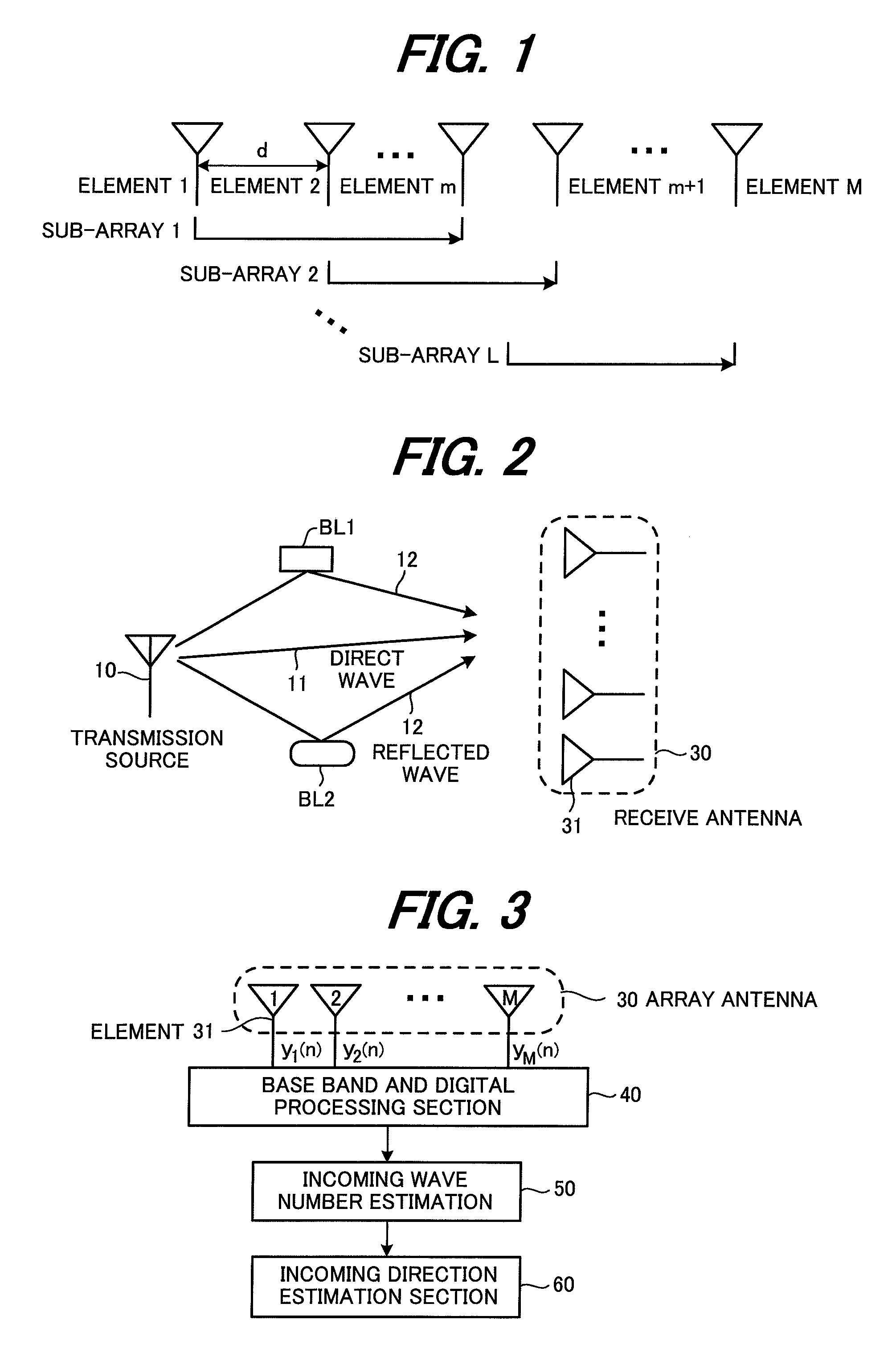
[0051]FIG. 1 is a diagram depicting a configuration of an array antenna in which M number of antenna elements are linearly arrayed with a spacing of distance d. FIG. 2 is a diagram depicting a positional relationship of a transmission source 10 and a base station receive antenna (array antenna) 30. As FIG. 1 shows, the array antenna 30 has a configuration of a uniform linear array antenna, and constitutes a multiple wave incoming direction estimation system. In FIG. 2, a direct wave 11 enters direc...

second embodiment

(B) Second Embodiment

[0086]In the first embodiment, the incoming wave number estimation method was described by creating the estimation matrix by

[0087]Φ^=[Φ^f,Φ_^f,Φ^b,Φ_^b],

but the incoming number of signals can be estimated for a complete correlation signal, that has multiple waves, or a partial correlation signal, or an uncorrelation signal, in an uncorrelated white noise environment by creating an estimation matrix {circumflex over (Φ)} using an arbitrary combination of the Hankel correlation matrix

[0088]Φ^f,Φ_^f,Φ^b,Φ_^b(A)

as described in connection with Expression (16).

[0089](a) Example of Using an Arbitrary One Set

[0090]Out of the four sets of correlation matrices in (A), one arbitrary matrix is selected, and an estimated matrix is created. In other words, an estimation matrix is created by one of the following expressions,

[0091]Φ^=Φ^f,Φ^=Φ_^f,Φ^=Φ^b,Φ^=Φ_^b(22)

and thereafter, the incoming wave number is estimated by the same method as the first embodiment.

[0092](b) Example o...

third embodiment

(C) Third Embodiment

[0098]The first and second embodiments are embodiments to estimate the incoming radio wave number in an uncorrelated white noise environment, where the correlations of the noise wi(n) and wj(n), included in the receive signals of the i-th antenna receive element and the j-th antenna receive element, are expressed by the following expressions.

E[wi(n)wj*(n)]=σ2 (i=j)

E[wi(n)wj*(n)]=0 (i≠j)

In other words, this is the case when the length of the spatial correlation of noise is 1. The third embodiment is the case when the length of the spatial correlation of noise is q (>1). If the length of the spatial correlation of the noise is q, the correlation of the noise wi(n) and wj(n), included in the receive signals of the i-th antenna receive element and the j-th antenna receive element, is expressed by the following expressions.

E[wi(n)wj*(n)]≠0 (|i−j|≦q)

E[wi(n)wj*(n)]=0 (|i−j|>q)

[0099]In other words, if the length of the spatial correlation of the noise is q, noise is i...


PUM


Abstract

An incoming wave number estimation device for receiving incoming radio waves by an array antenna in which a plurality (=M) of antenna elements are linearly arrayed with a same element spacing, and estimating the number of the incoming radio waves, including: a correlation matrix creation section for removing a diagonal element from a predetermined row or column constituting an M×M array covariance matrix, and creating a correlation matrix by extracting a predetermined p number of correlations from (M−1) number of correlations after the diagonal element is removed while sequentially shifting one element at a time, and arraying the p number correlations in a matrix; an estimation matrix creation section for creating an estimation matrix for estimating the incoming wave number using the correlation matrix; a QR decomposition section for performing QR decomposition on the estimation matrix; and an incoming wave number determination section for determining the number of incoming radio waves based on each row element of an upper triangular matrix factor obtained by the QR decomposition.

Description

BACKGROUND OF THE INVENTION[0001]The present invention relates to an incoming wave number estimation method, incoming wave number estimation device and radio device, and more particularly to an incoming wave number estimation method, incoming wave number estimation device and radio device for receiving incoming radio waves by an array antenna, where a plurality (=M) of antenna elements are linearly arrayed with a same element spacing, and estimating the number of incoming radio waves.[0002]Recently research and development using an adaptive array antenna for mobile communication is receiving attention, and a plurality of antenna elements arranged in different spatial positions in a certain form is called an “array antenna”. Estimation of an incoming direction of a radio wave (may also be called a “signal” from the standpoint of signal processing), which enters the antenna, is a critical elemental technology of an adaptive array antenna. In an actual mobile communication system, sign...

Claims


Application Information

Patent Timeline
Patent Type & Authority Patents(United States)
IPC IPC(8): G01S3/00
CPCH04B7/086G01S3/74
Inventor XIN, JINGMIN
Owner FUJITSU LTD
Why Eureka
Try Eureka