Liquid ejection head and image-forming apparatus using the same

a technology of image-forming apparatus and liquid ejection head, which is applied in the direction of printing, etc., can solve the problems of excessive distance between adjacent ejection openings, inability to achieve pitch, and inability to ensure position accuracy

Inactive Publication Date: 2008-11-18
CANON KK
View PDF34 Cites 4 Cited by
  • Summary
  • Abstract
  • Description
  • Claims
  • Application Information

AI Technical Summary

Benefits of technology

[0022]An object of the present invention is to provide, even in an image-forming apparatus capable of ejecting liquid droplets at a high frequency while scanning transverse to the feeding direction of a printing medium, a liquid ejection head adapted to restrict the deviation of the liquid droplets ejected even from ejection openings disposed in the respective opposite end section along the arrangement direction to prevent white streaks from generating in a solid printing and an image-forming apparatus using such an ejection head.
[0024]According to a first aspect of a liquid ejection head of the present invention, it is possible to adjust a position of the liquid droplet finally reached by the liquid droplet to a predetermined one on the printing medium, whereby a high-precision, multi-gradation and high-quality printed image free from white streaks is obtainable even if the solid printing is carried out. Particularly, when the arrangement pitch of the ejection openings forming an end group is longer from 0.1 to 10 μm than that of the ejection openings forming a central group, the effect of the present invention is more assuredly obtainable. If the difference is less than 0.1 μm, the effect resulted from the widening along the arrangement pitch is hardly obtainable, and also the positional accuracy is not ensured during the production process. Contrarily, if exceeding 10 μm, a distance between the adjacent ejection openings is excessively large to generate white streaks when the solid printing is carried out.
[0025]In the liquid ejection head according to the first aspect of the present invention, a diameter of the ejection opening forming the end group may be larger than that of the ejection opening forming the central group. Particularly, when the diameter of the ejection opening forming the end group is twice or less that of the ejection opening forming the central group, it is possible to prevent the white streaks from generating even if the solid printing is carried out by using a print head from which a liquid droplet does not so accurately reach the predetermined position on the printing medium. If exceeding twice, a concentration of the liquid droplet becomes excessively high to generate the irregularity in concentration as well as black streaks when a solid image is formed. In such a manner, it is effective to cause the difference in an arrangement pitch between the ejection openings in the end group and those in the central group to correspond to the difference in a diameter of the dot formed on the printing medium by the liquid droplet ejected from the ejection opening between the end group and the central group. It is also effective to further provide a plurality of liquid passages communicating the liquid to the ejection openings, and to design a width of the liquid passage communicated to the ejection openings forming the end group to be wider than that of the liquid passage communicated to the ejection opening forming the central group. Particularly, when the width of the liquid passage communicated with the ejection opening forming the end group is designed to be twice a width of the liquid passage communicated with the ejection opening forming the central group or less, it is unnecessary to lower the drive frequency applied to the corresponding ejection energy generating source even if an amount of the liquid droplet ejected from the ejection opening forming the end group increases, whereby the high speed driving can be maintained. If exceeding twice, a width of the liquid passage communicated with the ejection opening forming the central group becomes extremely small to lower the ejection frequency in the central group, whereby the printing speed is reduced.

Problems solved by technology

If the difference is less than 0.1 μm, the effect resulted from the widening along the arrangement pitch is hardly obtainable, and also the positional accuracy is not ensured during the production process.
Contrarily, if exceeding 10 μm, a distance between the adjacent ejection openings is excessively large to generate white streaks when the solid printing is carried out.
If exceeding twice, a concentration of the liquid droplet becomes excessively high to generate the irregularity in concentration as well as black streaks when a solid image is formed.

Method used


Image

  • Liquid ejection head and image-forming apparatus using the same
  • Liquid ejection head and image-forming apparatus using the same
  • Liquid ejection head and image-forming apparatus using the same

Examples


Embodiment Construction

[0051]One embodiment in which an image-forming apparatus according to the present invention is applied to an ink jet printer will be described in detail below with reference to FIGS. 1 to 10. The present invention, however, should not be limited to such embodiments but includes the combinations thereof or other technologies contained in the concept of the present invention defined by the scope of claim for the patent.

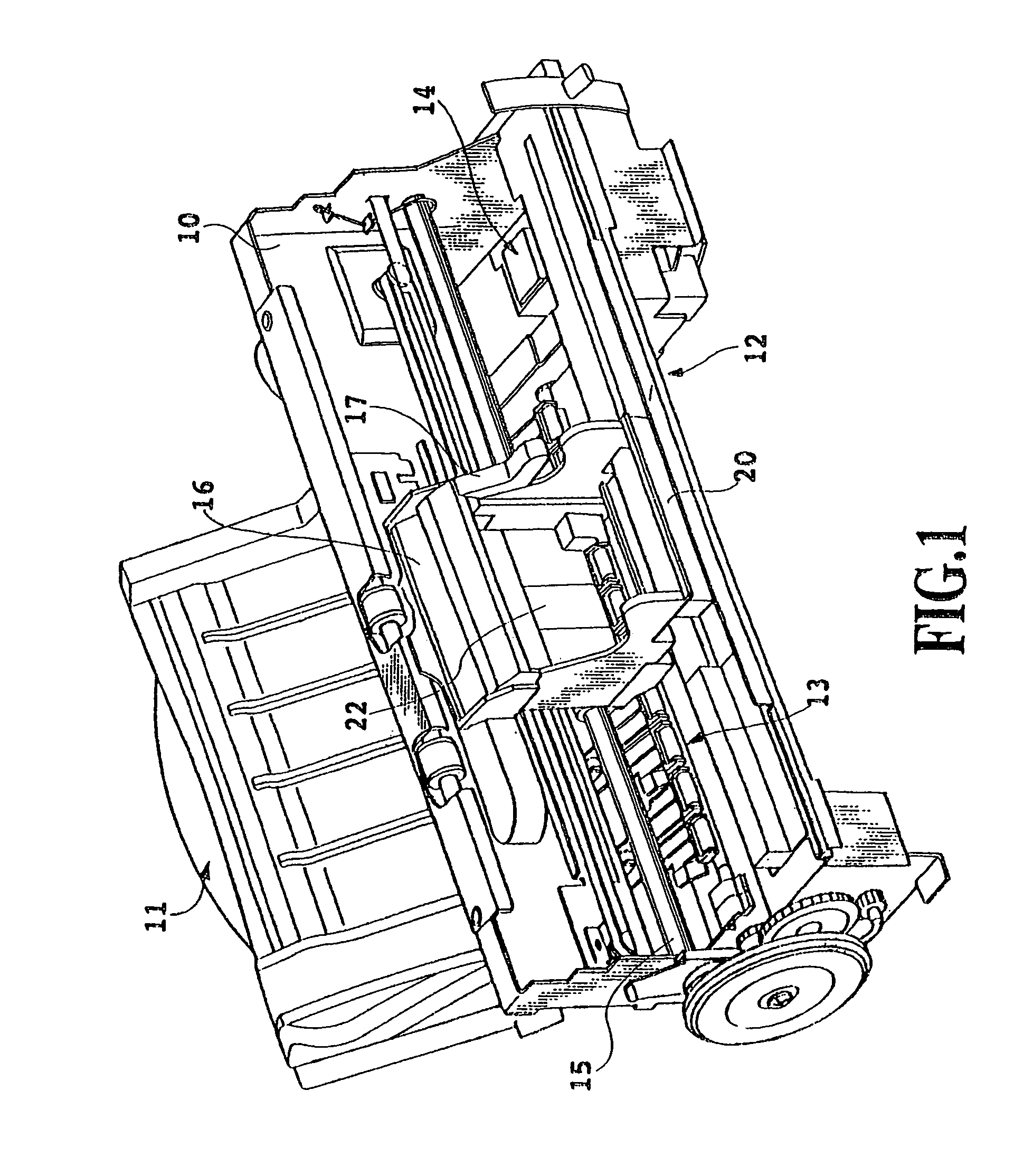
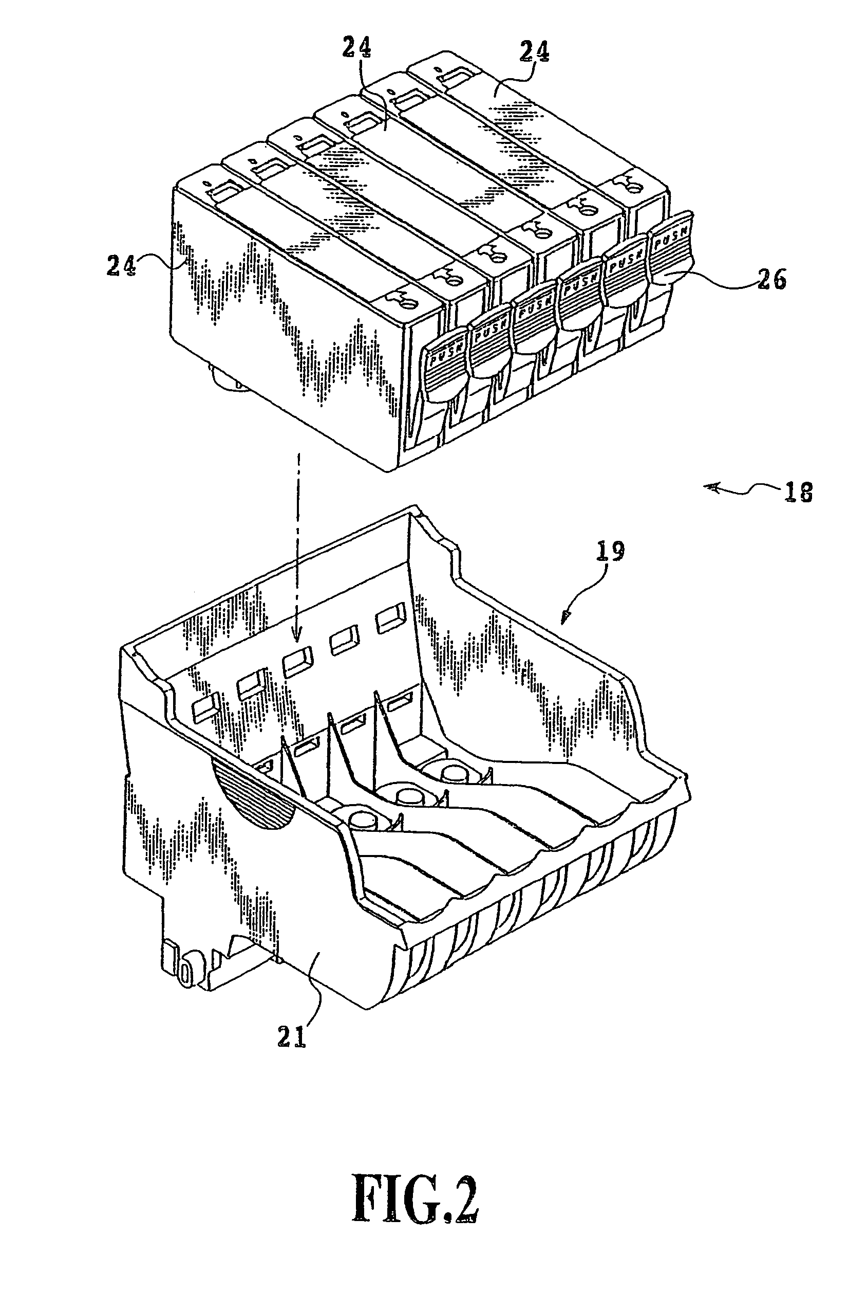
[0052]An appearance of a mechanism of an ink jet printer according to this embodiment is shown in FIG. 1; an appearance of the head cartridge used in this ink jet printer is shown in FIG. 2 in an exploded manner; and an appearance of a print head thereof is shown in FIG. 3. A chassis 10 of the ink jet printer of this embodiment consists of a plurality of pressed sheet metals having a predetermined rigidity to form a skeleton of the ink jet printer. In the chassis 10, there are incorporated a medium supplying part 11 for automatically feeding a printing medium not shown ...


PUM


Abstract

A liquid ejection head according to the present invention includes a plurality of ejection openings arranged in a first direction and a plurality of electro-thermal transducers for ejecting liquid from the ejection openings, the liquid ejection head and a printing medium being subjected to the relative movement, wherein an arrangement pitch of the ejection openings forming an end group located in the respective opposite end section along the first direction is longer than an arrangement pitch of the ejection openings forming a central group located in the central section along the first direction. According to the present invention, it is possible to eliminate white streaks which may generate in a solid printing.

Description

[0001]This is a continuation application of application Ser. No. 10 / 231,300, filed on Aug. 30, 2002 now abandoned.[0002]This application is based on Patent Application No. 2001-264733 filed Aug. 31, 2001 in Japan, the content of which is incorporated hereinto by reference.BACKGROUND OF THE INVENTION[0003]1. Field of the Invention[0004]The present invention relates to a liquid ejection head having openings for ejecting liquid and an image-forming device using the same.[0005]In this Specification, a word “print” refers to not only forming a significant information, such as characters and figures, but also forming images, designs or patterns on a printing medium and processing such as etching and so forth in the printing medium, whether the information is significant or insignificant or whether it is visible so as to be perceived by humans. The term “printing medium” includes not only paper used in common printing apparatus, but also sheet materials such as cloths, plastic films, metal...

Claims


Application Information

Patent Timeline
Patent Type & Authority Patents(United States)
IPC IPC(8): B41J2/21B41J2/14B41J2/15
CPCB41J2/14016B41J2/15B41J2002/14169
Inventor MIZUTANI, MICHINARIMURAKAMI, SHUICHI
Owner CANON KK
Why Eureka
Try Eureka