Hydrodynamically operated multifocal contact lens

a multi-functional, hydrodynamic technology, applied in the field of vision correction, can solve the problems of not providing a solution to the problem of most patients, making designs unacceptable to individuals with otherwise clear distance vision, etc., to achieve the effect of improving the range of patients, reducing the cost of lens replacement, and maintaining the position and comfort of the lens

Inactive Publication Date: 2008-11-18
IN TECH HLDG
View PDF6 Cites 29 Cited by
  • Summary
  • Abstract
  • Description
  • Claims
  • Application Information

AI Technical Summary

Benefits of technology

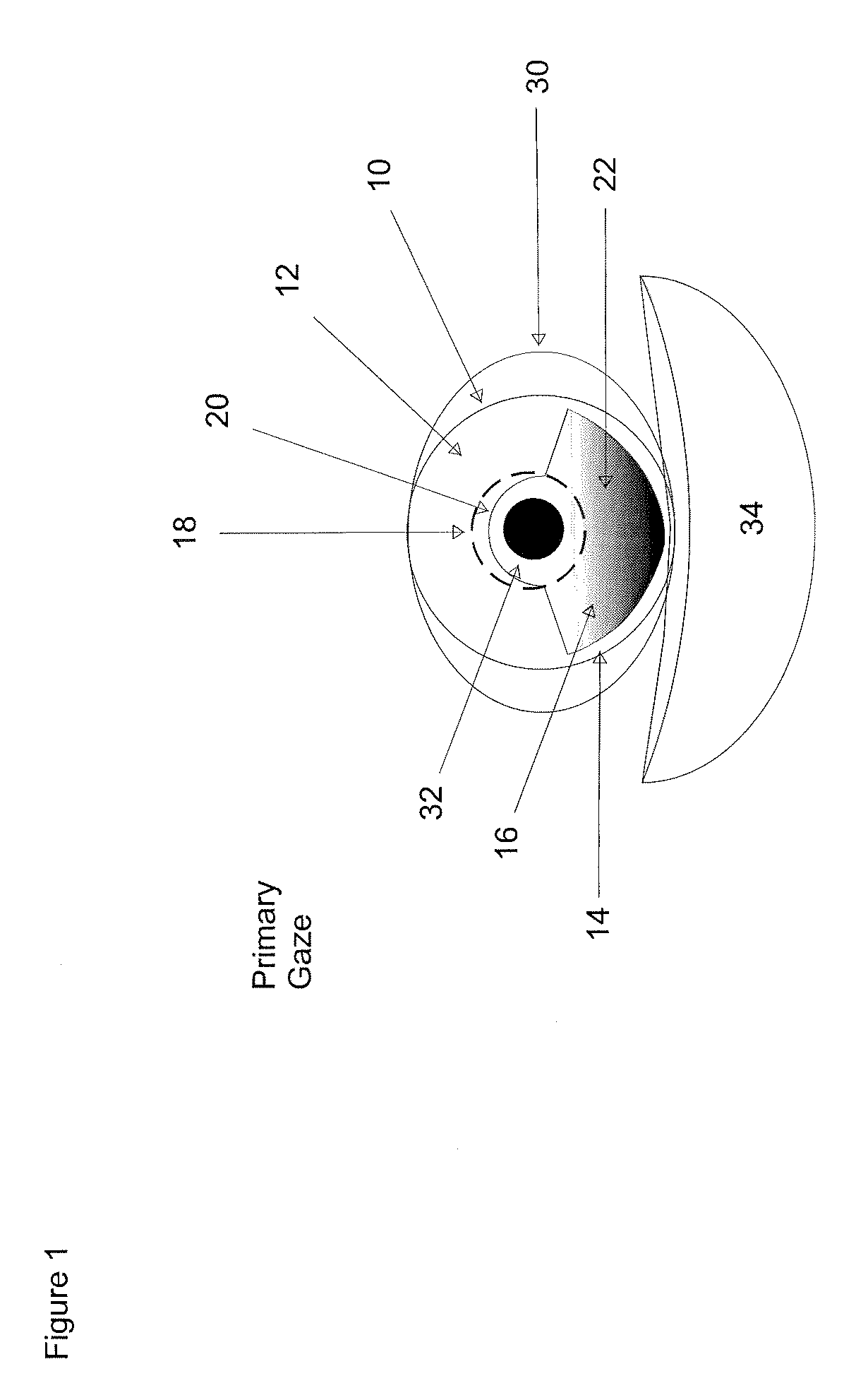
[0012]According to one embodiment of this invention a contact lens includes a reservoir filled with fluid. For distance viewing, the bulk of the fluid generally remains outside the wearer's optical axis. The reservoir is constructed and arranged so that it undergoes compression by the natural force of apposition of the lid applied to the eye itself during downward gaze. This compression forces fluid to move from the reservoir and into the internal chambers, thereby dynamically changing the shape of the lens, and thereby dynamically altering the optical characteristics of the contact lens. Conversely, when the wearer looks up the lens rides up from behind the lower lid thereby releasing the compression forces from the lid, allowing the fluid to return to the reservoir, thereby allowing the lens to return to its natural shape which is configured for distance vision. Thus, as described above, advantageously, in the present invention it is the position of gaze that determines the contact lens's optical characteristics in the field of vision. More specifically, the further the eye is in downward gaze the greater the change in the characteristics. Preferably, a downward gaze gradually changes the lenses focal point from the eye's distance vision to the eye's near vision. In effect this creates a continuous variable multifocal contact lens. This can be accomplished through using fluid pressure to reshape; squeeze the lens; or a combination of the above.
[0014]The use of a plurality of chambers, which can change shape through associated fluid movement responsive to nominal eyelid pressure, permits substantial changes in the optical characteristics of the lens. The dimensional changes occurring to the contact lens have designed features that would allow maximum refractive changes under minimum lid pressure while maintaining lens position and comfort. These features increase the range of patients able to gain benefit from reservoir lenses, especially considering that the pressure of lid apposition to the eye decreases with age. This invention also broadens the population of potential beneficiaries to include emmetropic presbyopes (individuals who only need correction for reading and not for distance) but whose eyelid pressure is insufficient for the reservoir lenses in the prior art as seen in Hydrodynamically Operated Multifocal Contact Lens. This invention is beneficial to this population because current products diminish the clarity at distance, which makes those designs unacceptable to individuals who otherwise have clear distance vision.
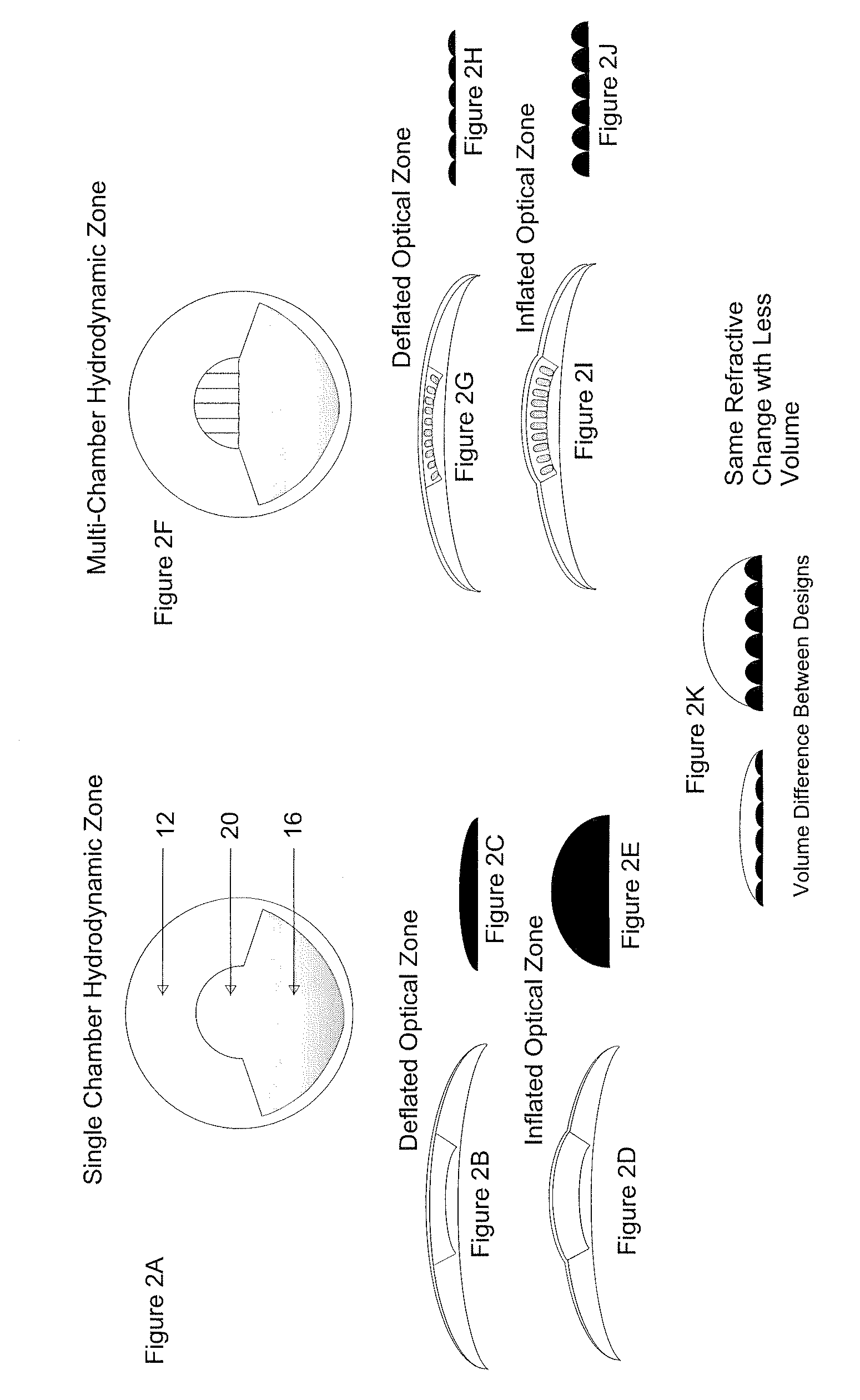
[0015]In another embodiment, the contact lens includes an internal cavity made up of a single reservoir combined with multiple chambers, or micro-channels or micro-tubes to allow for multiple small base cure changes instead of one large base curve change, thereby easing pressure required for fluid movement. Fluid exchange can be avoided completely by creating a diaphragm covering the base of the micro-channels leading into the optic zone. The diaphragm allows fluid pressure to be exchange between the peripheral reservoir and the central micro-channel optic zones without any fluid exchange, thereby eliminating contamination risks.

Problems solved by technology

Therefore, providing a contact lens having different refractive powers along different optical axes (as is the case with multifocal glasses) does not provide a solution to the problem of most patients.
This invention is beneficial to this population because current products diminish the clarity at distance, which makes those designs unacceptable to individuals who otherwise have clear distance vision.

Method used


Image

  • Hydrodynamically operated multifocal contact lens
  • Hydrodynamically operated multifocal contact lens
  • Hydrodynamically operated multifocal contact lens

Examples


second embodiment

[0037]the invention is shown in FIGS. 2F-2K. In this embodiment, the chamber 20 consists of a plurality of linear micro-channels 21 that extend across a substantial portion of section 18 of the eye and are in communication with the reservoir 16. When the contact lens 10 is placed into an eye 30, the reservoir 16 is disposed below the visual axis that passes the pupil 32. The reservoir 16 is filled with fluid, such as saline solution, contact lens lubricant, artificial tears or other non-toxic material such as liquid silicone or even an un-polymerized contact lens monomer. This fluid can be chosen to have refractive indices similar to, higher, or lower than the contact lens polymer, in order to effect the optical properties selected to provide near vision correction. Upon insertion, the weight of the reservoir causes the lens to take the position shown in the figures, i.e., with the reservoir disposed at the bottom portion of the lens.

[0038]When a wearer gazes straight forward for di...

third embodiment

[0045]In the invention, the micro-tubules 21 are not in direct communication with the reservoir 16 but are sealed like many small linear balloons with a flexible ends or diaphragms 24 (shown in FIGS. 3A, 3B) and contain a liquid 22A. These diaphragms are made of the same material that the micro-tubules are made of and are arranged so that when the wearer is gazing forward, the diaphragms are either relaxed (e.g. flat) or they bulge slightly downward to allow the micro-tubules 21 to flatten. When the wearer gazes downward, some of the fluid 22 flows upward causing the diaphragm to bulge upward and expand the micro-tubles 21 as shown in FIG. 2I. This embodiment is advantageous because the liquid from the reservoir 16 is separated from the liquid in the micro-tubules 21 thereby preventing cross-contamination which may cause optical hazing and therefore blurred vision. Moreover, the fluid in the chamber 20 and its micro-channels 21 could have a different index of refraction then the liq...

fourth embodiment

[0046]FIGS. 4A-4F show the invention. This embodiment also includes a reservoir 16 disposed at the bottom of contact lens 10 and having about the same size and shape as in the previous embodiments. However, the upper chamber 20 includes one or more annular micro-channels 11 encircling a sealed optic zone 19. The optic zone 19 is filled with a liquid, a gel, or a flexible solid and can exchange fluid or fluid pressure (through an appropriate diaphragm) from the reservoir 16 in the manner described for the other embodiments. When a wearer gazes forward for distance vision, the wearer looks along an optical axis that passes through section 19. In this position, the fluid in the surrounding ring 11 is primarily or totally disposed in the lower portion of the reservoir 16 as shown in FIGS. 4A and 4C causing the circumferential ring to be in a non-expanded or deflated state. In this configuration, the portion of the lens 19 through which the wearer is looking is configured to provide eith...


PUM


Abstract

This invention pertains to a soft contact lens that has a body with a central zone aligned with the optical axis of the eye when a wearer wears the lens. A micro-channel filled with fluid, is positioned at or near the optic zone and is arranged so that when the fluid is pressurized, the micro-channel expands and changes the optical characteristics of the central zone. The pressure in the microchannel is controlled through changes to a reservoir disposed in the lens below the optic zone.

Description

RELATED APPLICATIONS[0001]This application is related to copending U.S. application Ser. No. 11 / 326,261 filed Jan. 5, 2006 entitled Hydrodynamically Operated Multifocal Contact Lens, now pending; and to copending U.S. application Ser. No. 11 / 689,595 filed on Mar. 22, 2007 entitled “Manufacturing Techniques for Production of Hydrodynamic Multifocal Contact Lenses”, now pending, all incorporated herein by reference.BACKGROUND OF THE INVENTION[0002]a. Field of the Invention[0003]This invention deals with the art of vision correction through the application of a soft contact lens to the human eye. More particularly, this invention details a novel method to dynamically alter the optical characteristics of a soft contact lens by changing the shape of the lens using a fluid disposed therein.[0004]b. Description of the Prior Art[0005]The human eye contains two main tissues or elements that act to focus light onto the retina. The cornea, which is the clear, watch crystal-like tissue on the o...

Claims


Application Information

Patent Timeline
Patent Type & Authority Patents(United States)
IPC IPC(8): G02C7/04G02C7/02
CPCG02C7/041G02C7/085
Inventor IULIANO, MICHAEL J.
Owner IN TECH HLDG
Why Eureka
Try Eureka