

Hydrodynamically operated multifocal contact lens
- Summary
- Abstract
- Description
- Claims
- Application Information
AI Technical Summary
Benefits of technology
Problems solved by technology
Method used
Image

Examples
second embodiment
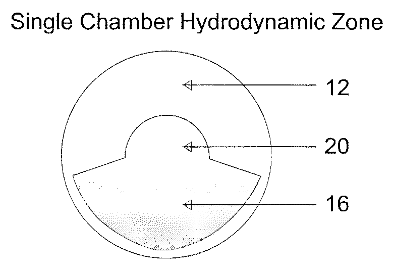
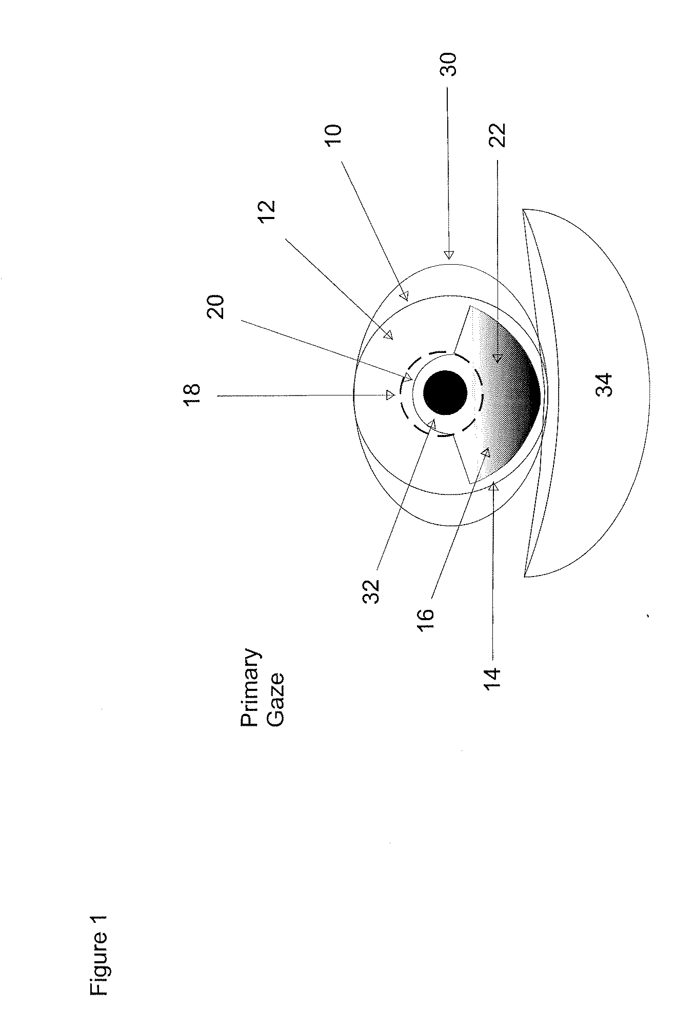
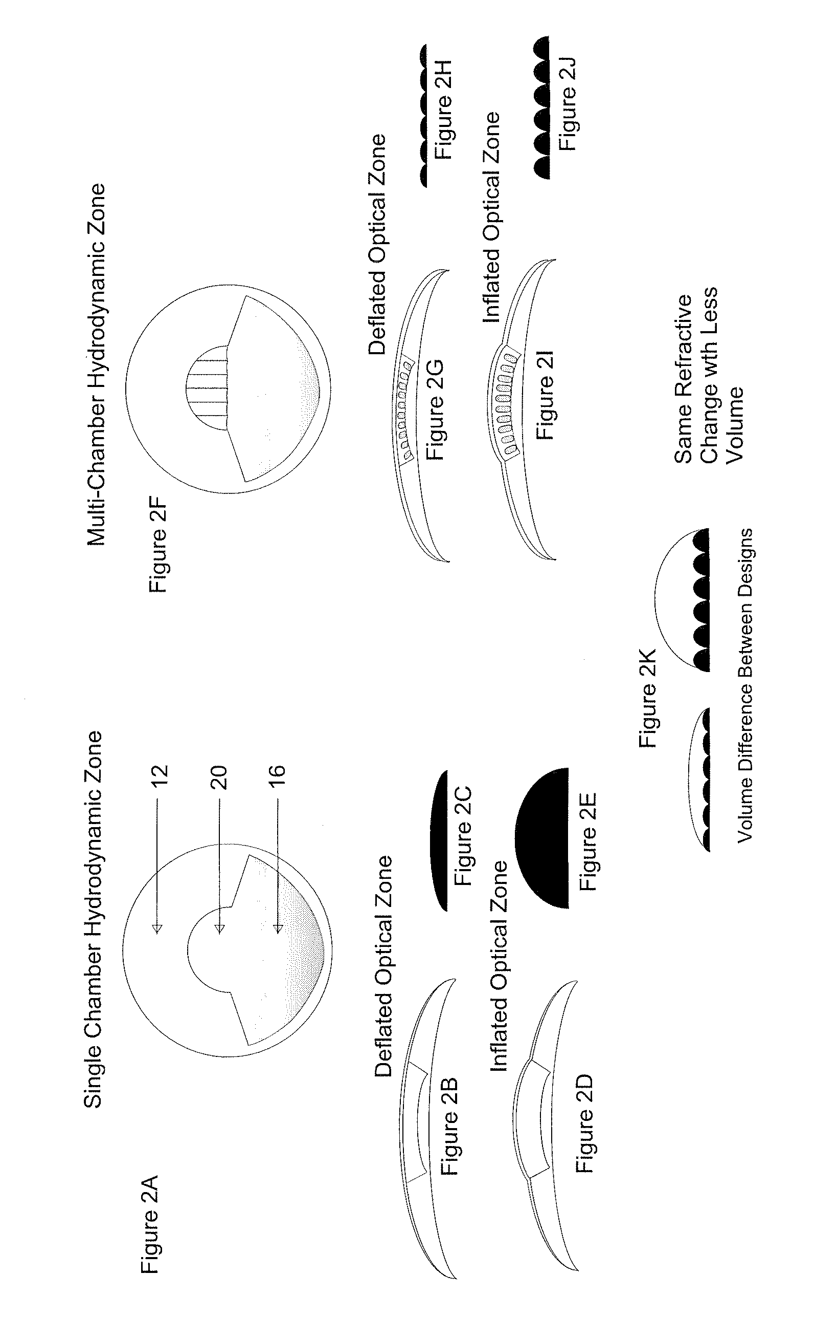
[0037]the invention is shown in FIGS. 2F-2K. In this embodiment, the chamber 20 consists of a plurality of linear micro-channels 21 that extend across a substantial portion of section 18 of the eye and are in communication with the reservoir 16. When the contact lens 10 is placed into an eye 30, the reservoir 16 is disposed below the visual axis that passes the pupil 32. The reservoir 16 is filled with fluid, such as saline solution, contact lens lubricant, artificial tears or other non-toxic material such as liquid silicone or even an un-polymerized contact lens monomer. This fluid can be chosen to have refractive indices similar to, higher, or lower than the contact lens polymer, in order to effect the optical properties selected to provide near vision correction. Upon insertion, the weight of the reservoir causes the lens to take the position shown in the figures, i.e., with the reservoir disposed at the bottom portion of the lens.
[0038]When a wearer gazes straight forward for di...
third embodiment
[0045]In the invention, the micro-tubules 21 are not in direct communication with the reservoir 16 but are sealed like many small linear balloons with a flexible ends or diaphragms 24 (shown in FIGS. 3A, 3B) and contain a liquid 22A. These diaphragms are made of the same material that the micro-tubules are made of and are arranged so that when the wearer is gazing forward, the diaphragms are either relaxed (e.g. flat) or they bulge slightly downward to allow the micro-tubules 21 to flatten. When the wearer gazes downward, some of the fluid 22 flows upward causing the diaphragm to bulge upward and expand the micro-tubles 21 as shown in FIG. 21. This embodiment is advantageous because the liquid from the reservoir 16 is separated from the liquid in the micro-tubules 21 thereby preventing cross-contamination which may cause optical hazing and therefore blurred vision. Moreover, the fluid in the chamber 20 and its micro-channels 21 could have a different index of refraction then the liq...
fourth embodiment
[0046]FIGS. 4A-4F show the invention. This embodiment also includes a reservoir 16 disposed at the bottom of contact lens 10 and having about the same size and shape as in the previous embodiments. However, the upper chamber 20 includes one or more annular micro-channels 11 encircling a sealed optic zone 19. The optic zone 19 is filled with a liquid, a gel, or a flexible solid and can exchange fluid or fluid pressure (through an appropriate diaphragm) from the reservoir 16 in the manner described for the other embodiments. When a wearer gazes forward for distance vision, the wearer looks along an optical axis that passes through section 19. In this position, the fluid in the surrounding ring 11 is primarily or totally disposed in the lower portion of the reservoir 16 as shown in FIGS. 4A and 4C causing the circumferential ring to be in a non-expanded or deflated state. In this configuration, the portion of the lens 19 through which the wearer is looking is configured to provide eith...
PUM
 Abstract
Description
Claims
Application Information